Soldering, Soldering, Soldering 🙂 Everything else had been following the amazingly well written guides of the LSM9DS0 made by sparkfun. Nine degrees of freedom at a rate of “a few per second”(currently 9Hz) since I’ve followed just the basic setup without fancy interrupt usage.
One thing thats really important to mention is the different signal voltage level of the SDA and SCL pins between the Micro(5V) and the IMU Breakout Board(3.3V) – which in case you connect them together without bi-directional level shifting, as you might expect since i2c is designed for exactly that, would lead to blue chip burn.
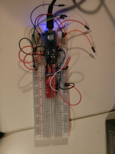
So wiring on the bread board (and not removing the wires used by the arduino motor shield v2, so do not get too confused by that):
and applying the library to the arduino IDE, leads to a working live example with 2 outputs per second: So the next step is to increase the rate by improving the setup wiring, parse that data into ROS Hydro by a SensorMsg/Imu publisher, kalman and combining these with other odom sources like my currently used (and sadly poor) or even an GPS source to a exact and really usable Odometry by the robot_pose_ekf package for later Simultaneous Localization and Mapping (SLAM) – a real autonomous mapping and navigation. Sounds easy right?

