Category Archives: Howtos

How to set up Arduino IDE for esp8266 programming

The Arduino (or in some cases also Genuino) is a physical hard and software development plattform. During the recent years its developing environment grow to a useful and library rich developing platform. Because of that the esp8266 team created an conversion tool to its internal programming language lua.

Setting up the Arduino IDE for esp8266 programming is really easy. Just follow this small guide.

Step 1: Download the arduino IDE software

Go to the most recent version download page of the Arduino IDE. Please keep in mind that you’ll need at least version 1.6.x. In some cases it is not available at the packet repositories of your beloved Debian Distribution.

screenshot-from-2016-12-28-15-22-44Click on Windows, Linux or Mac Version of your choice. We are going to use the Linux 64bit for further pictures.

screenshot-from-2016-12-28-15-24-53Extract the provided tar.gz. For windows or Mac please use a extraction software like 7zip, Winrar etc accordingly.

screenshot-from-2016-12-28-15-28-32Please make sure the arduino.sh file in your directory is excecutable.

screenshot-from-2016-12-28-15-28-49

screenshot-from-2016-12-28-15-29-01You also can use the terminal command:

chmod +x -/arduino.sh

After that double click the application…

screenshot-from-2016-12-28-15-33-03or use the terminal to start the IDE. This is also very useful to see possible errors after they occure while flashing the esp8266 from time to time.


screenshot-from-2016-12-28-15-33-21

Et voila, your IDE should look somehow like this:

screenshot-from-2016-12-28-15-34-45

Step 2: Setting up the IDE to work with ESP8266 by board manager.

We need to add an additional url to the boards manager sources list. For that open File > Preferences

screenshot-from-2016-12-28-15-37-55

And add http://arduino.esp8266.com/stable/package_esp8266com_index.json  to the Additional Boards Manager URLs.

screenshot-from-2016-12-28-15-38-25After that open Tools > Boards > Boards Manager and search for esp8266.

screenshot-from-2016-12-28-15-39-28

install the latest version:

screenshot-from-2016-12-28-15-40-02

After that you should be able to select the Generic ESP Module board in Tools > Board

screenshot-from-2016-12-28-15-41-22

screenshot-from-2016-12-28-15-42-15Congratulations! You are now able to compile esp8266 code from the arduino IDE.

Step 3: Use the Examples to learn to code

This step is easy. Open File > Examples > ESP8266Wifi > WifiWebServer as a good starting point.

screenshot-from-2016-12-28-18-12-55

In the next post we will have a look at how to wire the ESP8266 up for an easy flashing.

Controlling ws2812b with an esp8266 by open-pixel-control protocol

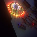
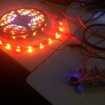
Harder than it looks but controlling an 5m led stripe using the esp8266 by the open pixel control protocol took me a night (and might be the reason for extra bad english as i write this post directly after it). But it’s real fun!

There are several ways to make the controller blink, the easiest way is shown here:

while true; do ( echo -en '\x00\x00\x02\xA6'; dd if=/dev/urandom bs=678 count=1 status=none ) | ncat --send-only --udp 172.22.99.155 2342; sleep 0.1; done

For the duration of infintiy, it sends the static header consisting of 4 bytes ( prio, command and checksum) followed by 8bit red 8bit green and 8bit blue for each led of the stripe. It gets the blinking values by asking the source of random in linux.  It lacks a bit of white as my power source got to its limits, so if you reimplement this use 5V and 1A per 30 leds.

Another thing to mention is the data length field which are bytes 3-4 of the header or \x02\xA6 as in the command above. This length needs to equal the amount of leds times three, so in this example 226 Leds where controlled as the bytes in network order end up to be 678.

This results in that little animation:

Youtube Video

Another possibility is to send these packets by a small python script like that:

import socket
import time

from struct import *

HOST = 'your-hostname'    
PORT = 2342              
colors = [(255,255,255), (255,0,0) ,(0,0,255), (0,255,0)  ]


for color in colors:
        print "sending color {} {} {}".format(color[0],color[1],color[2])
        data = [pack('b',0),pack('b',0), pack('!h',678)];

        for i in range(0,226):
                data.append(pack('BBB',color[0],color[1],color[2]))

        s = socket.socket(socket.AF_INET, socket.SOCK_DGRAM)


        for i in range(0,1024):
                s.sendto("".join(data),(HOST,PORT))

        time.sleep(0.5)
        s.close()

import pdb; pdb.set_trace()

Code for the controller at github.

Arduino microphone sensor analog + digital

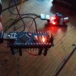
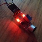
I tried a small arduino microphone recently:

int sensorPin = A0; // select the input pin for the potentiometer
int ledPin = 13; // select the pin for the LED
int sensorValue = 0; // variable to store the value coming from the sensor
 
void setup () 
{
  pinMode (ledPin, OUTPUT);
  Serial.begin (9600);
}
 
void loop () 
{
  sensorValue = analogRead (sensorPin);
  digitalWrite (ledPin, HIGH);
  delay (sensorValue);
  digitalWrite (ledPin, LOW);
  delay (sensorValue);
  Serial.println (sensorValue, DEC);
}

Output looks like that:

22
20
22
22
22
21
22
22
21
22
22
22
22
22
22
22
21
22
22
21


Well explaination how sound sensors work:

Youtube Video

Synchronize the time in ROS offline environments without chrony

As our [amazon &title=CubieTruck&text=CubieTruck] is faced with strange issues when using chrony and internet access is not a general prerequisite on ROS setups, i needed to figure out a new way to synchronize the time with no internet ntp server available. For some reasons, even my local ntp was broken, which is why I try to set the time according to the ros master on all clients by this simple bash command:

ntpdate `echo $ROS_MASTER_URI | grep -oE "b([0-9]{1,3}.){3}[0-9]{1,3}b"`

it simply extracts the IPv4 part of the $ROS_MASTER_URI environment and uses ntpdate to set the time on the excecuting client system.

In case you only want to know the exact time derivation consider using the ntpdate parameter -q which only emulates the request.

LaTeX borders around hyperref links and references

As I am currently writing my thesis and stumbled around the problem of borders around any reference (or link) inside the generated .pdf document, I first came around with an solution like that:

usepackage{hyperref}
hypersetup{
  colorlinks=false,
  allbordercolors=white
}

Which worked by setting all borders of hyperref to the color of white and therefore on a white document to an invisible color.

But later on, especially when programmatically writing tree graphs with background colors, this solution didn’t work anymore.

Which is why I needed to change the way of usage to:

usepackage[hidelinks]{hyperref}

instead of the previous block. Now there is no disturbing border anymore and teXing got a little better 🙂


asd

ROS – [rosout-1] process has died, exit code -11

Some days ago I started roscore and got faced with an error message like that:

process[rosout-1]: started with pid [16089]
[rosout-1] process has died [pid 16089, exit code -11, cmd /opt/ros/indigo/lib/rosout/rosout __name:=rosout __log:=/home/rosuser/.ros/log/9b3b3980-0b60-11e4-80f9-0015afdb2ab9/rosout-1.log].
log file: /home/rosuser/.ros/log/9b3b3980-0b60-11e4-80f9-0015afdb2ab9/rosout-1*.log

Okay, so roscore seemed to have crashed and created a log file according to the given path. But the logfile was empty *please imagine dramatic sound effects here*. But what do you do, if a programm (rosout?) crashes without log file and an error message like the above?

You insert your well done system wide backups like snapshots from zfs,btrfs, virtual machines, lvm or anything. If you forgot to do so… *fail sound here* you might need to manually check what changed since the last time it worked.

And so I did. For several days.

I soon figured out, that this error applied to all rosccp related ROS-programms – but left all rospy parts alive, which finally put my on track that there has been an kernel update of my ubuntu 14.04, which I unfortunately installed in a moment of weak decisions.
So reverting that would have been been an option, further my lib-boost version seemed to have changed – since ROS is very sensible to that, this might have been the problem. Therefore I tried everything by manually reverting updates, reinstalling packages, recompile everything from source, searching system logs and soon really considered to reset my system by installing good old 13.04 with ROS hydro…

But wait! Sometimes you strike lucky and time solves all issues. Today I’ve just upgraded my ROS from their repos and tadaaa – everything works again.

But why do I write this into an post? Because its easy to avoid situations like that and I want to share my hard learned lessons with you the easy way:

  1. Get your ROS version straight – Do you really need the latest ROS on the latest kernel?
    The answer for your system is probably no. I am currently running stable ROS Hydro and ‘unstable’ ROS Indigo on Ubuntu 14.04 on latest kernel. It works – but it would have been way easier to stick on Hydro all the way.
  2. avoid apt-get dist-upgrade on critical ROS machines
  3. use backups and / or virtual machines
  4. rospy didn’t cause any problems so far – in case performance isn’t the most important thing, think about using python
  5. avoid to put all your catkin_ws code into one git repository  if its running on multiple architectures (x86,x64, arm6,arm7) – alone the openni2_driver took nearly all my sanity during learning that lesson….

That is enough for today, but after this list, I really think about tracking all hard learned lessons in more public and better organised location – ROS best practices? We’ll see.


show apt-get history in Ubuntu / Debian

Sometimes you need some information about your apt-get install / upgrade / remove history. (for example if you destroyed your ROS-Install on your laptop).

By adding a little code snippet to your .bashrc you achieve a very useful tool.

function apt-history(){
      case "$1" in
        install)
              cat /var/log/dpkg.log | grep 'install '
              ;;
        upgrade|remove)
              cat /var/log/dpkg.log | grep $1
              ;;
        rollback)
              cat /var/log/dpkg.log | grep upgrade | 
                  grep "$2" -A10000000 | 
                  grep "$3" -B10000000 | 
                  awk '{print $4"="$5}'
              ;;
        *)
              cat /var/log/dpkg.log
              ;;
      esac
}

Now running

apt-history install
[...]
2014-07-14 19:08:13 install ros-indigo-desktop-full:i386 <none> 1.1.3-0trusty-20140711-1919-+0000

brings you all install entries with timestamp and version information.  Note: instead of install ‘upgrade‘ and ‘remove‘ works too. ‘rollback‘ brings you version information you’ll might need for what I now call downgrade.

Reset Arduino Micro via python serial

Sometimes resetting a device isn’t as easy as expected. After some research i figured out, that opening a serial connection with a special baud rate would to the job for our Arduino Micro (and similiar like Leonardo):

#!/usr/bin/env python


import serial
port='/dev/ttyACM0' #adjust this in case your device differs
ser = serial.Serial() #open serial connection
ser.port=port #setting the port accordingly

#in case your usual baudrate isn't 9600 reset will not work, therefore we will open a resetable connection
#thanks to mattvenn.net for suggesting to add this step!
ser.baudrate=9600
ser.open(); ser.close()

ser.baudrate=1200 # set the reset baudrate
ser.open(); ser.close()
#don't forget to sleep some reset time

Run the script as root. It might need required to change your port according to your serial controller status.

Arduino Micro and 3.3V IMU LSM9DS0 9DOF

Soldering, Soldering, Soldering 🙂 Everything else had been following the amazingly well written guides of the LSM9DS0 made by sparkfun. Nine degrees of freedom at a rate of “a few per second”(currently 9Hz) since I’ve followed just the basic setup without fancy interrupt usage.

One thing thats really important to mention is the different signal voltage level of the SDA and SCL pins between the Micro(5V) and the IMU Breakout Board(3.3V) – which in case you connect them together without bi-directional level shifting, as you might expect since i2c is designed for exactly that, would lead to blue chip burn.

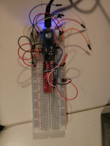
So wiring on the bread board (and not removing the wires used by the arduino motor shield v2, so do not get too confused by that):

IMG_20140612_192126

and applying the library to the arduino IDE, leads to a working live example with 2 outputs per second:ScreenshotIMULSM9DS0So the next step is to increase the rate by improving the setup wiring, parse that data into ROS Hydro by a SensorMsg/Imu publisher,  kalman and combining these with other odom sources like my currently used (and sadly poor)  or even an GPS source to a exact and really usable Odometry by the robot_pose_ekf package for later Simultaneous Localization and Mapping (SLAM) – a real autonomous mapping and navigation. Sounds easy right?

Using TU-BAF VPN on Ubuntu with NetworkManager and VPNC

Using the VPN of the Technical University Bergakademie Freiberg on Ubuntu 14.04 and previous version can be really easy. Please check if you are running NetworkManager like you should by default.

Now install the network-manager-vpnc extension by:

sudo apt-get update && sudo apt-get install -y network-manager-vpnc

Using system settings > Network Connections, or the nm-applet (the small network icon in your task bar) > Edit Connections
you should be able to follow this images:ScreenshotNMApplet

ScreenshotAddVPNScreenshotAddVPN2Now set the empty fields to the values below, for user name, choose your default credential:

ScreenshotAddVPN3

click on Advanced button:ScreenshotAddVPN4

Now the VPN should start by clicking inside the nm-applet:

ScreenshotAddVPN5

Please also see the official pages (german):

http://tu-freiberg.de/urz-21
http://urz.tu-freiberg.de/urz/netze/vpn/index.html