Category Archives: Sensors

Leap Motion in a low cost robotics context

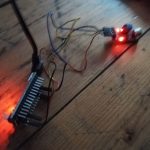
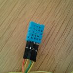
As partner of ASUS  the Leap Motion uses the same emitted and reflected infrared light for tracking parts of the human body like the Asus Xtion Pro . Available since July 2013, the Leap Motion with about 90EUR is an inexpensive, but limited input device,  which is optimized for tracking fingers and hands as illustrated in the following illustrations.

LeapMotionVisualization

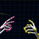
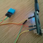
LeapMotion Visualization API allows track- ing of two hands and advanced gesture recognition

LeapMotionDevice

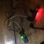
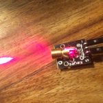
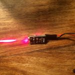
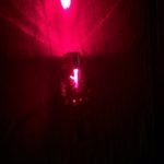
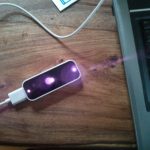
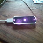
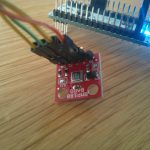
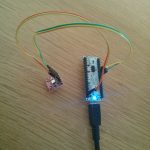
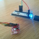
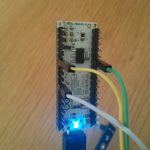
LeapMotion device emits infrared light, which can be seen with a non-filtered camera

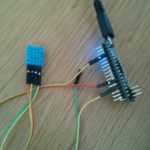
The main features include the tracking of two simultaneous hands with gesture recognition for all ten fingers. For distances between 10cm and 1m at daylight the device works reliably.

During my thesis, I have tested the existing ROS driver, which currently only supports one hand and was not able to provide 3D PointCloud data. In brief, the Leap Motion unfortunately is inappropriate for our project as their only use could be unreliable robot control by hand gestures.

5V Light Detector analog / digital ‘Flying Fish – MH Sensor Series”

Took me a while to find the purpose of this little device I had in the mail recently. it’s a light detection sensor, which I connected to the arduino nano to test its functionality. it servs the amount of light from 0 (very bright) to 1024 (very dark) using the analog pin. To use this device with the ESP8266 you’ll probably need to adapt the voltage and transform it between 0-1V.  But for now, it works fine costing around 2 EUR 🙂

 void setup ()
int sensorPin = A0; // select the input pin for the potentiometer
int ledPin = 13; // select the pin for the LED
int sensorValue = 0; // variable to store the value coming from the sensor
 
void setup () 
{
  pinMode (ledPin, OUTPUT);
  Serial.begin (9600);
}
 
void loop () 
{
  sensorValue = analogRead (sensorPin);
  digitalWrite (ledPin, HIGH);
  delay (sensorValue);
  digitalWrite (ledPin, LOW);
  delay (sensorValue);
  Serial.println (sensorValue, DEC);
}

Output looks like this (analog):

21 -> bright
90
68
63
81
81
83
89
78
85
99
558
897
822
882
864 -> dark

5V 5mW Laser Sensor Module for Arduino 650nm

Ok, calling it a sensor is a bit off… as it only is cabable of beeing turned on and off again. Measurements for a 0.85 EUR device would be a real surprise, but hey – the cats still love the beam which is easily mountable to an robotic arm consisting of two 28-BYJ stepper motors 🙂

 void setup ()
 {
   pinMode (13, OUTPUT); 
 }

void loop () {
    digitalWrite (13, HIGH); / / open the laser head
    delay (1000); / / delay one second
    digitalWrite (13, LOW); / / turn off the laser head
    delay (1000); / / delay one second
 }


Arduino microphone sensor analog + digital

I tried a small arduino microphone recently:

int sensorPin = A0; // select the input pin for the potentiometer
int ledPin = 13; // select the pin for the LED
int sensorValue = 0; // variable to store the value coming from the sensor
 
void setup () 
{
  pinMode (ledPin, OUTPUT);
  Serial.begin (9600);
}
 
void loop () 
{
  sensorValue = analogRead (sensorPin);
  digitalWrite (ledPin, HIGH);
  delay (sensorValue);
  digitalWrite (ledPin, LOW);
  delay (sensorValue);
  Serial.println (sensorValue, DEC);
}

Output looks like that:

22
20
22
22
22
21
22
22
21
22
22
22
22
22
22
22
21
22
22
21


Well explaination how sound sensors work:

Youtube Video

LeapMotion and ROS

Today I’ve got the chance to get my hands on a Leap Motion. As it uses depth information to track hands on a short range from the device and as there is a ros driver package existing for it, I hoped to get a 3D PointCloud. It costs about 80€ and could have been a cheap replacement for the [amazon &title=Xtion&text=Asus Xtion].

Unfortunately its not possible (yet?) – here is a very nice post why.

But it is fun anyways to get both hands tracked:

Youtube Video

The ros driver interfaces ros with only one hand – but we could do something like shown below to control the amosero:

Youtube Video

Later it would be a nice way to control a robot arm – but for now we leave that nice little device as there is a lot of other stuff to be done.

ROS Hydro/Indigo and sparkfun IMU LSM9DS0 9DOF

I’ve connected the LSM9DS0 9 degrees of Freedom Breakout Board made by sparkfun with an arduino micro like I’ve described in a previous post, wrote a little rosserial sensor_msgs::Imu publisher and visualized everything using the rqt plugin manager for further experimenting.

Here a screenshot while moving the setup:

ScreenshotIMURos

a screenshot while not touching:

ScreenshotIMURos2

As you see all data is still moving a lot. So the next step beside finding out what the units really mean, will be stabilizing by using a kalman filter like its provided in the robot_pose_ekf package.

By the way: the arduino is currently using around 25000 of its 28 672 bytes memory just providing the IMU data to ros. So the motorshield will require another micro or we switch it to something else like an wiimote.

Arduino Micro and 3.3V IMU LSM9DS0 9DOF

Soldering, Soldering, Soldering 🙂 Everything else had been following the amazingly well written guides of the LSM9DS0 made by sparkfun. Nine degrees of freedom at a rate of “a few per second”(currently 9Hz) since I’ve followed just the basic setup without fancy interrupt usage.

One thing thats really important to mention is the different signal voltage level of the SDA and SCL pins between the Micro(5V) and the IMU Breakout Board(3.3V) – which in case you connect them together without bi-directional level shifting, as you might expect since i2c is designed for exactly that, would lead to blue chip burn.

So wiring on the bread board (and not removing the wires used by the arduino motor shield v2, so do not get too confused by that):

IMG_20140612_192126

and applying the library to the arduino IDE, leads to a working live example with 2 outputs per second:ScreenshotIMULSM9DS0So the next step is to increase the rate by improving the setup wiring, parse that data into ROS Hydro by a SensorMsg/Imu publisher,  kalman and combining these with other odom sources like my currently used (and sadly poor)  or even an GPS source to a exact and really usable Odometry by the robot_pose_ekf package for later Simultaneous Localization and Mapping (SLAM) – a real autonomous mapping and navigation. Sounds easy right?

Arduino Micro and temperature+humidity sensor DHT11

Today is sensor day, so I’ve managed to get the [amazon &title=DHT11&text=DHT11] working:

Wire it like that:
([amazon &title=DHT11&text=DHT11] -> Arduino Micro )

  • Pin 1 (orange cable) to 5V
  • Pin 2 (yellow cable) to GND
  • Pin 3 – not needed
  • Pin 4 (yellow again -.-) to A0

Use the following code I’ve found here:

#include <dht.h>

#define dht_dpin A0 //no ; here. Set equal to channel sensor is on

dht DHT;

void setup(){
  Serial.begin(9600);
  delay(300);//Let system settle
  Serial.println("Humidity and temperaturenn");
  delay(700);//Wait rest of 1000ms recommended delay before
  //accessing sensor
}//end "setup()"

void loop(){
  //This is the "heart" of the program.
  DHT.read11(dht_dpin);

    Serial.print("Current humidity = ");
    Serial.print(DHT.humidity);
    Serial.print("%  ");
    Serial.print("temperature = ");
    Serial.print(DHT.temperature); 
    Serial.println("C  ");
  delay(800);//Don't try to access too frequently... in theory
  //should be once per two seconds, fastest,
  //but seems to work after 0.8 second.
}// end loop()

Getting you a result like that:

It doesn’t seem to be very accurate, but that’s expectable rated by its low price (<2€)


Arduino Micro and barometric pressure sensor BMP180

I’ve experimented with the [amazon &title=BMP180&text=BMP180].  Since its a 3,3V breakout board which is I²C capable I had concerns since the Micro usually uses 5V on its Pins. But without a reason: the I²C on the[amazon &title=BMP180&text=BMP180] needs to get a voltage of 5V and the arduino micro also provides 3.3.
So wiring all together:

Breakout Board -> [amazon &title=Arduino Micro&text=Arduino Micro]
DA -> SDA (Digital 2)
CL -> SCL (Digital 3)
+ -> 3.3 (do NOT plug this to 5V!)
-> GND

Sparkfun offers very good tutorials and source code. The library you’ll need to run this board can be found here

Getting this into your Arduino IDE leads to:

Since its an I²C device it should be stackable with any other I²C device in case they do not have the same BUS-address.


Arduino Micro and temperature sensor LM35

Using the LM35 with the Micro is quite easy.

Just connect:
(LM35 -> [amazon &title=Arduino Micro&text=Arduino Micro] )

  • 5V to positiv
  • GND to
  • S to A4

And run the following code (should run on every arduino):

float temp;
int tempPin = 4;

void setup()
{
  Serial.begin(9600);
}

void loop()
{
  temp = analogRead(tempPin);
  temp = temp * 0.48828125;
  Serial.print("TEMPRATURE = ");
  Serial.print(temp);
  Serial.print("*C");
  Serial.println();
  delay(1000);
}

Getting this result:

Please note its you might need to adjust the 0.48828125 to a value thats verified with another temperature sensor (or just a normal celsius thermometer) .

The next step for me is to write a little ROS publisher for this sensor.