Category Archives: Robotics

How to set up Arduino IDE for esp8266 programming

The Arduino (or in some cases also Genuino) is a physical hard and software development plattform. During the recent years its developing environment grow to a useful and library rich developing platform. Because of that the esp8266 team created an conversion tool to its internal programming language lua.

Setting up the Arduino IDE for esp8266 programming is really easy. Just follow this small guide.

Step 1: Download the arduino IDE software

Go to the most recent version download page of the Arduino IDE. Please keep in mind that you’ll need at least version 1.6.x. In some cases it is not available at the packet repositories of your beloved Debian Distribution.

screenshot-from-2016-12-28-15-22-44Click on Windows, Linux or Mac Version of your choice. We are going to use the Linux 64bit for further pictures.

screenshot-from-2016-12-28-15-24-53Extract the provided tar.gz. For windows or Mac please use a extraction software like 7zip, Winrar etc accordingly.

screenshot-from-2016-12-28-15-28-32Please make sure the arduino.sh file in your directory is excecutable.

screenshot-from-2016-12-28-15-28-49

screenshot-from-2016-12-28-15-29-01You also can use the terminal command:

chmod +x -/arduino.sh

After that double click the application…

screenshot-from-2016-12-28-15-33-03or use the terminal to start the IDE. This is also very useful to see possible errors after they occure while flashing the esp8266 from time to time.


screenshot-from-2016-12-28-15-33-21

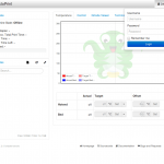
Et voila, your IDE should look somehow like this:

screenshot-from-2016-12-28-15-34-45

Step 2: Setting up the IDE to work with ESP8266 by board manager.

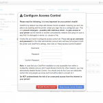
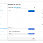
We need to add an additional url to the boards manager sources list. For that open File > Preferences

screenshot-from-2016-12-28-15-37-55

And add http://arduino.esp8266.com/stable/package_esp8266com_index.json  to the Additional Boards Manager URLs.

screenshot-from-2016-12-28-15-38-25
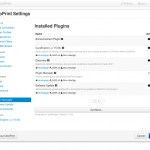
After that open Tools > Boards > Boards Manager and search for esp8266.

screenshot-from-2016-12-28-15-39-28

install the latest version:

screenshot-from-2016-12-28-15-40-02

After that you should be able to select the Generic ESP Module board in Tools > Board

screenshot-from-2016-12-28-15-41-22

screenshot-from-2016-12-28-15-42-15Congratulations! You are now able to compile esp8266 code from the arduino IDE.

Step 3: Use the Examples to learn to code

This step is easy. Open File > Examples > ESP8266Wifi > WifiWebServer as a good starting point.

screenshot-from-2016-12-28-18-12-55

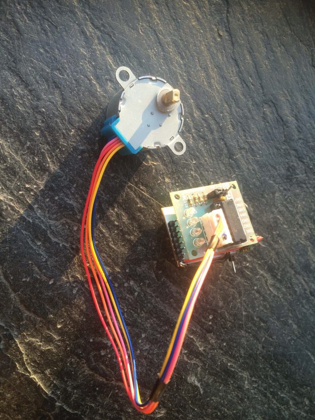
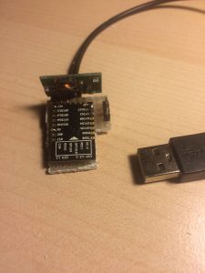
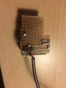
In the next post we will have a look at how to wire the ESP8266 up for an easy flashing.

Building a wifi LiquidCrystal-Display esp8266 for less than 10 EUR

As planned, I now built and esp8266 version of the display. Because the breadboard version was working quite well from the start, I decided to build a more permanent version.  The 5V of the USB Cable (or any other 5V Source) gets stepped down by a LM2596 circuit in a Fp6190 I purchased some time ago. This is a quite cheap and energy efficient solution. The complete setup requires about 70mA at 5Vs. This surely can be optimized by dimming the brightness of the display. In case you want to build your own wifi LiquidCrystal-Display esp8266 use the details provided below and check the code on Github. Happy hacking!

Parts List

  • 2,00€ ESP8266 12-Q
  • 2,00€ Fp6190 5V to 3.3V step down converter
  • 1,50€ LiquidCrystal-Display Blue
  • 1.6kOhm resistor or 10k potentiometer
  • prototyping board
  • cables
  • pins


Wiring

 LCD    -> ESP8266 12-Q
 following pinmap http://arduino.esp8266.com/versions/1.6.5-1160-gef26c5f/doc/esp12.png
  --------------------------
  1|VSS| -> USB GND
  2|VDD| -> USB 5V +5v
  3|VO | -> USB GND pin + 1,6k ohm Resistor
  4|RS | -> ESP2866  pin 4
  5|RW | -> ESP2866 GND
  6|E  | -> ESP2866 pin 5
 11|D4 | -> ESP2866 pin 13
 12|D5 | -> ESP2866 pin 12
 13|D6 | -> ESP2866 pin 14
 14|D7 | -> ESP2866 pin 16
 15|A  | -> GND + no or a below 10k Resistor  to dimm background light (Backlight power)
 16|K  | -> USB GND (Backlight ground)

Code

This time on GitHub.


3 axis 28BYJ-48 ROS controllable flash light

I have found a bit older project of mine while browsing through my photos.. on a relatively unclean desk you can see a combination of two 28BYJ-48 motors, some screws, metal parts and a flashlight. Last of them could be replaced for example by a laserpointer, simple sensor or a distance measurement device.

Originally this was created to be placed on my amosero robot as a very simple form of an robot arm. Sadly work forced me to not follow that project side track any further which is why I can’t share more than these pictures: IMG_0068 Maybe some when if time allows, I will recreate this and make it more accessible.

Octoprint - M33-Fio - Raspberry Pi - select positions on the print bed

Running M3D Micro under Raspbian with Octoprint and MD3Fio plugin

The M3D Software is windows only, which causes a lot of wasted power by running a windows machine all time. After several and some successful attempts of running this software on a virtual machine inside my Linux, I figured out a much more easy way to print from a Raspberry Pi. It’s called Octoprint, but on an armhf basis requires a bit attention. In combination with the M33-Fio Plugin its serving perfectly as a printing server for the M3D-Micro I own.

Setting up your Raspberry Pi 3

To save me and you some time in future, I share the step by step code to set up an Raspberry Pi 3 with Octoprint from scratch. (even if there is an image down-loadable from Octroprint Website)

#allow pi user to communicate with printer via tty
sudo usermod -a -G tty pi
sudo usermod -a -G dialout pi

#install cura slicing engine by compiling it from source
cd ~
sudo apt-get install -y python-wxgtk2.8 python-numpy
git clone https://github.com/daid/Cura.git
cd Cura
#installing the requirements of Cura
sudo pip install -r requirements.txt
mkdir CuraEngine
cd CuraEngine
wget -OCuraEngine http://octoprint.org/files/octopi/cura_engine_14.12/cura_engine
chmod +x CuraEngine
cd ..
{ echo '#!/bin/sh'; echo 'PYTHONPATH=. python2 -m Cura.cura "$@"'; } > cura.sh
#also if we don't use the wrapper, we still make it executable
chmod +x cura.sh

#install octoprint
cd ~
sudo apt-get install -y python-pip python-dev python-setuptools python-virtualenv git libyaml-dev build-essential
git clone https://github.com/foosel/OctoPrint.git
cd OctoPrint
virtualenv venv
./venv/bin/pip install pip --upgrade
./venv/bin/python setup.py install
#install the requirements
sudo pip install -r requirements.txt
#install the m3d (or m33) fio plugin
sudo /usr/bin/pip install https://github.com/donovan6000/M33-Fio/archive/master.zip
mkdir ~/.octoprint
ufw allow 5000
./run

Start using Octoprint in browser

Start your browser at 127.0.0.1:5000 (or the ip of your rasbperry) and config Octoprint further:

Happy printing! With this combination of 3-5 Watt Raspberry Pi, and a maximum 20W M3D you can run the printer 24/7 without wasting more than a light bulb amount of power 🙂

Links:

28BYI-48 stepper motor with Wifi - final setup

Controlling a 28BYI-48 stepper motor with Wifi for less than 10$ USD by using an esp2866 12-q

For low cost robots, remote controlled laser pointers, cat or fish feeding machines I found a really cheap way to move things by programmable wifi. The already handy usable 28BYJ-48 coming small motor driver i board is  available in china for about 2$. It additionally needs to be driven by a fast micro controller like the Arduino or the much more capable Raspberry Pi.  As I was experimenting with the esp2866 12-Q recently, the combination of this two useful things seemed more than obvious.  Therefore I decided to give it a try.

Unfortunately the stepper motor and its driver chip the ULN2003a need at least 5Vs to run, a voltage the esp2866 would by killed by as its maximum rating is about 3.6. in conclusion two power circuits or two power sources would be required. I tried to keep things simple by using an 5V-12V power source and step down converting it to 3.3V with an lm2655 based step down circuit. This setup allows an efficiency about 95% and avoids producing high amounts of heat as linear step down converters would have done. Overall the motor and the controllers consume 0.35 Amps at 5V therefore about 1.75 Watts.

Parts

  • 2$ 28BYJ-48 with ULN2003a motor driver
  • 2$ esp8266
  • 2$ step-down-converter
  • > 0,5$ breadboard 2.5 mm adapter for the esp8266
  • > 0,.5$  for15 cm of additional cables low diameter
  • soldering equipment and an 3.3V FTDI Adapter for flashing the esp2866

Steps to build your own:

  1. solder the esp2866 on the adapter board
  2. reverse the in1 in2 in3 in4 pins to the other side of the motor driver ULN2003a  board
  3. put the breadboard adapter on this pins starting with vcc followed by in1 to in4
  4. connect the v_out of the step down circuit with vcc of the breadboard adapter
  5. connect v_in of the step down circuit to the vcc of the motor driver board
  6. connect all GNDs together
  7. add pins on the breadboard adapter for flasingh the esp2866, GND, VCC, TX and RX
  8. flash the esp2866 with
    https://github.com/PaulPetring/esp2866-28BYJ-48-motor-control/blob/master/simple.ino
  9. test solderinng and apply between 5V an 12V connected to the motor driver board
  10. have fun 🙂

Wiring concept

Video on Youtube

https://github.com/PaulPetring/esp2866-28BYJ-48-motor-control

Leap Motion in a low cost robotics context

As partner of ASUS  the Leap Motion uses the same emitted and reflected infrared light for tracking parts of the human body like the Asus Xtion Pro . Available since July 2013, the Leap Motion with about 90EUR is an inexpensive, but limited input device,  which is optimized for tracking fingers and hands as illustrated in the following illustrations.

LeapMotionVisualization

LeapMotion Visualization API allows track- ing of two hands and advanced gesture recognition

LeapMotionDevice

LeapMotion device emits infrared light, which can be seen with a non-filtered camera

The main features include the tracking of two simultaneous hands with gesture recognition for all ten fingers. For distances between 10cm and 1m at daylight the device works reliably.

During my thesis, I have tested the existing ROS driver, which currently only supports one hand and was not able to provide 3D PointCloud data. In brief, the Leap Motion unfortunately is inappropriate for our project as their only use could be unreliable robot control by hand gestures.

ROS Basics – challenges in the robotic low cost context

Applications in robotics need to solve a lot of computational intensive tasks. While some of them can be outsourced to an externally powered device like a laptop or a server, others essentially can be calculated on the UGV.

Examples for that are collecting sensor data, receiving and executing commands or streaming data. Balancing these is a challenging task, because on concurrent executing systems all processes can influence each other. Especially when computational power gets cut down to the limits in order to save energy. As most libraries, frameworks or software environments do, ROS requires additional resources when being compared to a single purpose application.

In conclusion providing enough computational power while using reasonable amounts of energy is an important task to solve.

Physical properties
Physical dimensions and requirements result from a tradeoff between costs and size, whereas smaller UGVs tend to be more expensive and complex. On the other hand, an upper bound among others is set by being manageable in terms of transport and storage.

The low cost target UGV is a four wheel or two tracks driven ground robot with physical dimensions below 150mm * 300mm * 300mm (height, width, length). The drive power should be accordingly with an effective force of more than 100 Ncm for moving or holding torque in case of stronger slope. Additionally, tracks are the preferred primary propulsion system as they have better grip properties and only require simple motor control. Another nice to have would be the capability of spot-turning, which would allow operating on small areas and facilitates 3D scans of rooms without moving further than required. Another optional point if the robot is going to be used outside of buildings or around kids is a splash-proof case that would increase the robots life. Furthermore, modular extensibility would increase the usability of the robot significantly.

Modular design

In order to solve the tremendous requirements of robotics in a low cost context, we need to think out of the box while structuring the challenges in solvable problems. Like the following graph shows, we should divide the functionality of UGVs into four main modules: First, Sensors are the parts the robot requires to sense the outside world, next Accumulators serving and saving power, followed by Processors the units are processing information gathered by Sensors and finally, Actuators which provide physical movement. These areas in turn get separated into further sections which we discuss one by one on the next posts.

Screenshot_2016-03-11_21-40-35

ROS Basics – ROS in a low cost robotic context

UGVs like they are found in industry, education or Do it yourself (DIY) communities are currently not affordable for average technique enthusiasts, teachers in schools or sometimes even universities. The concept of low cost robots tries to solve that issue.

What is low cost in a robotic context?

The traditional interpretation of low cost is minimizing the expenses while keeping most important features. In borders of mostly expensive robotics this term needs to follow the same differentiation as between cheap , which means coming with a significantly reduced price and quality, and keen , considered as maintaining a certain amount of quality at a reduced total cost. For example, the 50 000 USD UBR1 is a low cost version 250 000 USD up to 400 000 USD PR2  of Willow Garage , but still is far away from the term cheap in a common way . Another example and at the same time another robot Melonee Wise worked on is the TurtleBot , which was constructed with the attempt to be the lowest cost version of a ROS robot at time of creation.1

How to achieve low cost?

There is no general solution to this problem. But an approach to solve the issue in the robotic context is to replace expensive single purpose solutions produced by companies in low quantities with mass produced products that get customized to suit the application.
A demonstration of this positive misuse are the first versions of the TurtleBot . Instead of constructing the robot with expensive 3D Laser Scanners they replaced it by a Microsoft Kinect originating from the gaming industry. Furthermore, it used a iRobot Roomba and later a iRobot Create as a low cost mobile base as constructing a custom movable footprint would
have been way more expensive. Also, the mass produced product came at a lower cost and unharmed warranty. An important side-effect of these replaceable parts is the independence of unique cost intensive and sometimes, due to customs regulations, not easily accessible parts. By that, the power to choose a cheap replacement at any time reduces overall expenses and
total risk.

As a consequence, an low cost UGV should be easy to build and reproduce, affordable for education and able to run ROS with some kind of 3D measuring device. It further should consist of easily achievable or replaceable parts.
In conclusion, these properties lead to a modular design concept with communication inter- faces between the inexpensive components. Also a certain degree of flexibility is required to maintain extensibility and independence of expensive parts.

esp8266 ws2812b hostname triggered wifi light

Today I built a small wifi light which rotates in case a certain hostname (my smartphone) is in the local wifi. As these devices tend not to answer to ping or arp requests, and bonjour or mDNS where to slow, I crawl my dhcp server every five to ten seconds. Additionally i decreased the lease time of the dhcp to  improve the switch off response time. As my smartphone usually logs into my wifi instantly when I enter the house it’s usually switches on before the main door has been opened.

The interior of the lamp consists of seventeen ws2812b rgb leds which I controlled in an intermediate stage with the esp2866 opc code on github. As this would have required a constant network packages flow and a device delivering the UDP packages, I later on switched over to control the led animation by the esp8266.

Something I discovered today is that soldering the 2mm grid esp8266 upside down onto a 2.54 grid prototyping circuit board improves handling and speed, as well as the size of the final circuit.  You also can see the pin map information on the final product, which is nice.

After putting some hot glue on the board to prevent shorts and improve lifetime, I took some measurements regarding current consumption: about 0,1Amps at 5V, which should result to 0.5W with a constant rotating light and wifi crawling. This makes the device capable to be run on most USB power providers. The final result looks like this in action:

Youtube

As the code is very specific and dependent on my local setup, I will not post it on github this time. Just one thing I would have found really helpful to find in the internet while I was struggling with a constantly without information resetting esp8266 would have been this:

Howto grab and parse a HTTP.Auth protected website with the esp8266 as a client:

bool getPage() {
  bool foundHost = false;

  WiFiClient client; //initialising the client globally leads to crashes

  if (client.connect(http_site, 80)) { //the more common version !client.connect() crashes 

    // We now create a URI for the request
    String url = "/dhcp";
    
    // This will send the request to the server
    client.print(String("GET ") + url + " HTTP/1.1\r\n" +
                 "Host: " + http_site + "\r\n" +
                 "Authorization: Basic YWRTeW4kYWRmaW4=\r\n" + //this is Http.Auth as a Client (Base 64)
                 "Connection: close\r\n\r\n");
    delay(500); // you'll need to wait until repsonse
    String line = "";
    // Read all the lines of the reply from server and print them to Serial
    while (client.available()) {
      line = client.readStringUntil('\r');
      //Serial.print(line);
      if (line.indexOf(hostname) != -1) {
        foundHost = true;
        break;
      }
    }
  } else {
    Serial.println("connection failed");
  }
}

In conclusion, this was a nice little project I really enjoyed doing in a sleepless night 🙂 And with about 10€ plus the lamp I got as a gift a long time ago, not that expensive.

Controlling ws2812b with an esp8266 by open-pixel-control protocol

Harder than it looks but controlling an 5m led stripe using the esp8266 by the open pixel control protocol took me a night (and might be the reason for extra bad english as i write this post directly after it). But it’s real fun!

There are several ways to make the controller blink, the easiest way is shown here:

while true; do ( echo -en '\x00\x00\x02\xA6'; dd if=/dev/urandom bs=678 count=1 status=none ) | ncat --send-only --udp 172.22.99.155 2342; sleep 0.1; done

For the duration of infintiy, it sends the static header consisting of 4 bytes ( prio, command and checksum) followed by 8bit red 8bit green and 8bit blue for each led of the stripe. It gets the blinking values by asking the source of random in linux.  It lacks a bit of white as my power source got to its limits, so if you reimplement this use 5V and 1A per 30 leds.

Another thing to mention is the data length field which are bytes 3-4 of the header or \x02\xA6 as in the command above. This length needs to equal the amount of leds times three, so in this example 226 Leds where controlled as the bytes in network order end up to be 678.

This results in that little animation:

Youtube Video

Another possibility is to send these packets by a small python script like that:

import socket
import time

from struct import *

HOST = 'your-hostname'    
PORT = 2342              
colors = [(255,255,255), (255,0,0) ,(0,0,255), (0,255,0)  ]


for color in colors:
        print "sending color {} {} {}".format(color[0],color[1],color[2])
        data = [pack('b',0),pack('b',0), pack('!h',678)];

        for i in range(0,226):
                data.append(pack('BBB',color[0],color[1],color[2]))

        s = socket.socket(socket.AF_INET, socket.SOCK_DGRAM)


        for i in range(0,1024):
                s.sendto("".join(data),(HOST,PORT))

        time.sleep(0.5)
        s.close()

import pdb; pdb.set_trace()

Code for the controller at github.