Parsoid 0.9.0 update brings 406 Not Acceptable docserver error in VisualEditor REL_30 on Mediawiki 1.30

Some of my mediawiki instances broke when editing a page with VisualEditor on REL_30 today bringing HTTP 416 Errors related to Parsoid.

Strangely this error only occured when editing  existing pages, simplyfied as curl below:

curl "http://NAME_OF_WIKI_HERE/api.php?action=visualeditor&format=json&paction=parse&page=Main_Page&uselang=en"


{"error":{"code":"apierror-visualeditor-docserver-http","info":"HTTP 406","*":"See http://NAME_OF_WIKI_HERE/api.php for API usage. Subscribe to the mediawiki-api-announce mailing list at <https://lists.wikimedia.org/mailman/listinfo/mediawiki-api-announce> for notice of API deprecations and breaking changes."}}%

After a while I found that parsoid announced the behavoiur on there github rep:

This release requires clients (VE, etc.) to return a 1.6.0 and greater HTML version string in the header. If not, Parsoid will return a HTTP 406. This can be fixed by updating VE (or relevant clients) to a more recent version.

Unfortunately I used their .deb repository  releases.wikipedia.org which didn’t provide the 0.8.0 package for reverting the update. And since I’ve already updated  -marking it on hold in apt was no longer an option.

After reading a bit through the source code the solution I found until the next mediawiki stable versions arrives can be followed by editing the

lib/config/ParsoidConfig.js

and switch this line:

ParsoidConfig.prototype.strictAcceptCheck = true;

to that

ParsoidConfig.prototype.strictAcceptCheck = false; //true;

It’s not pretty, but for now it solved my issues.

Robot Thoughts

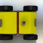
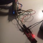
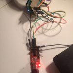
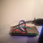
Friends of mine and myself met and discussed an advanced robot design. Here some impressions:


How to set up Arduino IDE for esp8266 programming

The Arduino (or in some cases also Genuino) is a physical hard and software development plattform. During the recent years its developing environment grow to a useful and library rich developing platform. Because of that the esp8266 team created an conversion tool to its internal programming language lua.

Setting up the Arduino IDE for esp8266 programming is really easy. Just follow this small guide.

Step 1: Download the arduino IDE software

Go to the most recent version download page of the Arduino IDE. Please keep in mind that you’ll need at least version 1.6.x. In some cases it is not available at the packet repositories of your beloved Debian Distribution.

screenshot-from-2016-12-28-15-22-44Click on Windows, Linux or Mac Version of your choice. We are going to use the Linux 64bit for further pictures.

screenshot-from-2016-12-28-15-24-53Extract the provided tar.gz. For windows or Mac please use a extraction software like 7zip, Winrar etc accordingly.

screenshot-from-2016-12-28-15-28-32Please make sure the arduino.sh file in your directory is excecutable.

screenshot-from-2016-12-28-15-28-49

screenshot-from-2016-12-28-15-29-01You also can use the terminal command:

chmod +x -/arduino.sh

After that double click the application…

screenshot-from-2016-12-28-15-33-03or use the terminal to start the IDE. This is also very useful to see possible errors after they occure while flashing the esp8266 from time to time.


screenshot-from-2016-12-28-15-33-21

Et voila, your IDE should look somehow like this:

screenshot-from-2016-12-28-15-34-45

Step 2: Setting up the IDE to work with ESP8266 by board manager.

We need to add an additional url to the boards manager sources list. For that open File > Preferences

screenshot-from-2016-12-28-15-37-55

And add http://arduino.esp8266.com/stable/package_esp8266com_index.json  to the Additional Boards Manager URLs.

screenshot-from-2016-12-28-15-38-25After that open Tools > Boards > Boards Manager and search for esp8266.

screenshot-from-2016-12-28-15-39-28

install the latest version:

screenshot-from-2016-12-28-15-40-02

After that you should be able to select the Generic ESP Module board in Tools > Board

screenshot-from-2016-12-28-15-41-22

screenshot-from-2016-12-28-15-42-15Congratulations! You are now able to compile esp8266 code from the arduino IDE.

Step 3: Use the Examples to learn to code

This step is easy. Open File > Examples > ESP8266Wifi > WifiWebServer as a good starting point.

screenshot-from-2016-12-28-18-12-55

In the next post we will have a look at how to wire the ESP8266 up for an easy flashing.

Building a wifi LiquidCrystal-Display esp8266 for less than 10 EUR

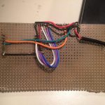
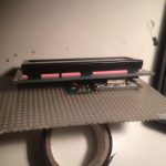
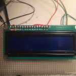
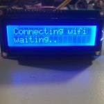
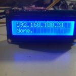
As planned, I now built and esp8266 version of the display. Because the breadboard version was working quite well from the start, I decided to build a more permanent version.  The 5V of the USB Cable (or any other 5V Source) gets stepped down by a LM2596 circuit in a Fp6190 I purchased some time ago. This is a quite cheap and energy efficient solution. The complete setup requires about 70mA at 5Vs. This surely can be optimized by dimming the brightness of the display. In case you want to build your own wifi LiquidCrystal-Display esp8266 use the details provided below and check the code on Github. Happy hacking!

Parts List

  • 2,00€ ESP8266 12-Q
  • 2,00€ Fp6190 5V to 3.3V step down converter
  • 1,50€ LiquidCrystal-Display Blue
  • 1.6kOhm resistor or 10k potentiometer
  • prototyping board
  • cables
  • pins


Wiring

 LCD    -> ESP8266 12-Q
 following pinmap http://arduino.esp8266.com/versions/1.6.5-1160-gef26c5f/doc/esp12.png
  --------------------------
  1|VSS| -> USB GND
  2|VDD| -> USB 5V +5v
  3|VO | -> USB GND pin + 1,6k ohm Resistor
  4|RS | -> ESP2866  pin 4
  5|RW | -> ESP2866 GND
  6|E  | -> ESP2866 pin 5
 11|D4 | -> ESP2866 pin 13
 12|D5 | -> ESP2866 pin 12
 13|D6 | -> ESP2866 pin 14
 14|D7 | -> ESP2866 pin 16
 15|A  | -> GND + no or a below 10k Resistor  to dimm background light (Backlight power)
 16|K  | -> USB GND (Backlight ground)

Code

This time on GitHub.


Smart Electronics LCD Module Display Monitor 1602 5V Blue

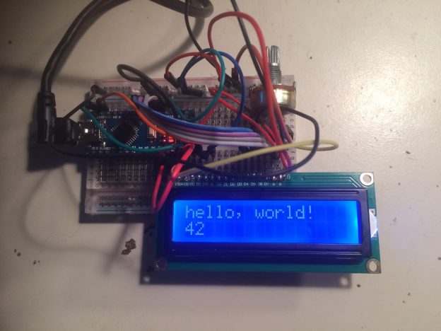
LiquidCrystal-Display blue 1602 Arduino Nano

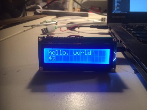
I recently bought several “Smart Electronics LCD Module Display Monitor 1602 5V Blue” for building a wifi alarm clock. It uses the very common Hitachi HD44780 driver. To verify if they are working I followed this well described tutorial on arduino.cc and used a arduino nano for that. Removing the 10k ohms resistor, because it dimmed the LED background light way to much and after adjusting the potentiometer to about 1,64k ohms the visibility of desired output was optimal.

For the sake of documentation the:

Wiring

 LCD    -> Arduino
  --------------------------
  1|VSS| -> Arduino GND
  2|VDD| -> Arduino +5v
  3|VO | -> Arduino GND pin + 1,6k ohm Resistor or Potentiometer
  4|RS | -> Arduino pin 12
  5|RW | -> Arduino GND - pin can be conected to 11. But Ground was used here.
  6|E  | -> Arduino pin 11
 11|D4 | -> Arduino pin 5
 12|D5 | -> Arduino pin 4
 13|D6 | -> Arduino pin 3
 14|D7 | -> Arduino pin 2
 15|A  | -> GND + no or a below 10k Resistor  to dimm background light (Backlight power)
 16|K  | -> Arduino GND (Backlight ground)

Code

#include <LiquidCrystal.h>

// initialize the library with the numbers of the interface pins
LiquidCrystal lcd(12, 11, 5, 4, 3, 2);

void setup() {
  lcd.display();
  // set up the LCD's number of columns and rows:
  lcd.begin(16, 2);

  lcd.print("hello, world!");
}

void loop() {
  // set the cursor to column 0, line 1 (second row)
  lcd.setCursor(0, 1);
  // print the number of seconds since reset:
  lcd.print(millis() / 1000);
}

The next step is to connect it to an esp8266 and figuring out if the new 3.3V signal strength will be enough. A possible solution would be to use the esp8266 only as a communication device.

FritzBox Python Class Fritz OS 6.30+ syncing Google Calendar

This project allows to interact with your FritzBox above the new FritzOS 6.30 to 6.60 (tested with Fritzbox 7490 and 7390) by using a self written FritzBox Python Class. It furthermore uses the Google Calendar API to enter phonecalls and online devices status into your google calendar. To use the Google Services you will need to generate your own client api credentials including a valid calendar json. For the expected format see the provided default files.

Of course the FritzBox Python Script also works stand alone, an provides following functionality:

  • read out last 400 phone calls
  • list current network devices

Of course I plan to increase that functionality:

  • add a config.json
  • implement CalDav Support for non google solutions
  • add pictures of google calendar entries
  • enable gant charts of devices (d3js?)
  • get FritzBox phone book(s)
  • sync phone books to Google Contacts
  • sync phone books to CardDav

I’ve you are interested to use or join me developing:

https://github.com/PaulPetring/FritzBox

General Usage FritzBox python class

#constructors
box = FritzBox()
box = FritzBox("password") # should be default constructor
box = FritzBox("password", "username")
box = FritzBox("password", "username", "http://fritz.box")
box = FritzBox("password", "username", "http://fritz.box",false)

# getting a list of active devices as objects of FritzBoxDevice
devices = box.get_devices(self,"active")

# getting a list of passive devices as objects of FritzBoxDevice
devices = box.get_devices(self,"passive")

# getting a list of objects of FritzBoxCall
calls = box.get_foncalls()

# getting a list of objects of FritzBoxFonBookEntry
fon_book = box.get_fonbook()

General Usage Google Calendar Wrapper

For phone calls:

fon_calendar = GoogleCalendarWrapper("YOUR_CALENDAR_ID@group.calendar.google.com")
fon_events = fon_calendar.get_events()
handleFonEntriesToGoogleCalendar(fon_calendar,fon_events,calls)

For active devices tracking:

devices_calendar = GoogleCalendarWrapper("YOUR_CALENDAR_ID@group.calendar.google.com")
device_events = devices_calendar.get_events()
handleDeviceEntriesToGoogleCalendar(devices_calendar,device_events,devices)


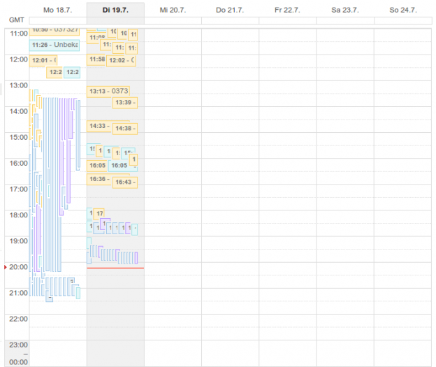
This also works for multiple FritzBoxes, here you see all phone calls of a week:

FritzBox Python Class - calendar view

FritzBox Python Class – calendar view

It’s pretty easy to add this script to a raspberry pi located in the network of the router. You’ll also can setup an vpnc connection between the box and an server or use a dynamic ip and a custom port.

3 axis 28BYJ-48 ROS controllable flash light

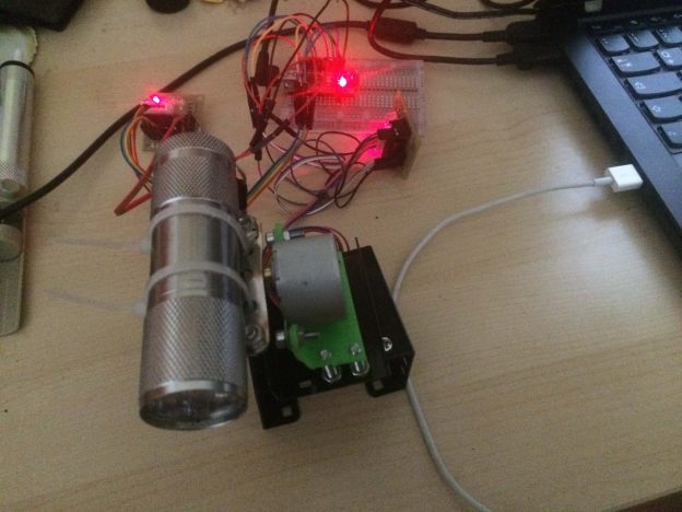
I have found a bit older project of mine while browsing through my photos.. on a relatively unclean desk you can see a combination of two 28BYJ-48 motors, some screws, metal parts and a flashlight. Last of them could be replaced for example by a laserpointer, simple sensor or a distance measurement device.

Originally this was created to be placed on my amosero robot as a very simple form of an robot arm. Sadly work forced me to not follow that project side track any further which is why I can’t share more than these pictures: IMG_0068 Maybe some when if time allows, I will recreate this and make it more accessible.

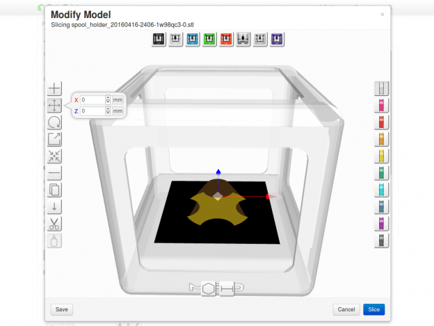
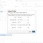
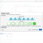
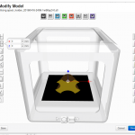
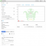
Octoprint - M33-Fio - Raspberry Pi - select positions on the print bed

Running M3D Micro under Raspbian with Octoprint and MD3Fio plugin

The M3D Software is windows only, which causes a lot of wasted power by running a windows machine all time. After several and some successful attempts of running this software on a virtual machine inside my Linux, I figured out a much more easy way to print from a Raspberry Pi. It’s called Octoprint, but on an armhf basis requires a bit attention. In combination with the M33-Fio Plugin its serving perfectly as a printing server for the M3D-Micro I own.

Setting up your Raspberry Pi 3

To save me and you some time in future, I share the step by step code to set up an Raspberry Pi 3 with Octoprint from scratch. (even if there is an image down-loadable from Octroprint Website)

#allow pi user to communicate with printer via tty
sudo usermod -a -G tty pi
sudo usermod -a -G dialout pi

#install cura slicing engine by compiling it from source
cd ~
sudo apt-get install -y python-wxgtk2.8 python-numpy
git clone https://github.com/daid/Cura.git
cd Cura
#installing the requirements of Cura
sudo pip install -r requirements.txt
mkdir CuraEngine
cd CuraEngine
wget -OCuraEngine http://octoprint.org/files/octopi/cura_engine_14.12/cura_engine
chmod +x CuraEngine
cd ..
{ echo '#!/bin/sh'; echo 'PYTHONPATH=. python2 -m Cura.cura "$@"'; } > cura.sh
#also if we don't use the wrapper, we still make it executable
chmod +x cura.sh

#install octoprint
cd ~
sudo apt-get install -y python-pip python-dev python-setuptools python-virtualenv git libyaml-dev build-essential
git clone https://github.com/foosel/OctoPrint.git
cd OctoPrint
virtualenv venv
./venv/bin/pip install pip --upgrade
./venv/bin/python setup.py install
#install the requirements
sudo pip install -r requirements.txt
#install the m3d (or m33) fio plugin
sudo /usr/bin/pip install https://github.com/donovan6000/M33-Fio/archive/master.zip
mkdir ~/.octoprint
ufw allow 5000
./run

Start using Octoprint in browser

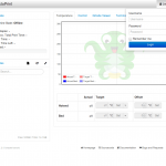
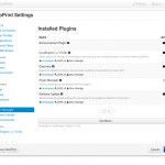
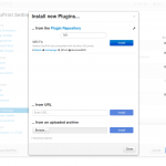
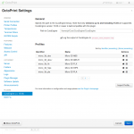
Start your browser at 127.0.0.1:5000 (or the ip of your rasbperry) and config Octoprint further:

Happy printing! With this combination of 3-5 Watt Raspberry Pi, and a maximum 20W M3D you can run the printer 24/7 without wasting more than a light bulb amount of power 🙂

Links: