Category Archives: Actuators

3 axis 28BYJ-48 ROS controllable flash light

I have found a bit older project of mine while browsing through my photos.. on a relatively unclean desk you can see a combination of two 28BYJ-48 motors, some screws, metal parts and a flashlight. Last of them could be replaced for example by a laserpointer, simple sensor or a distance measurement device.

Originally this was created to be placed on my amosero robot as a very simple form of an robot arm. Sadly work forced me to not follow that project side track any further which is why I can’t share more than these pictures: IMG_0068 Maybe some when if time allows, I will recreate this and make it more accessible.

28BYI-48 stepper motor with Wifi - final setup

Controlling a 28BYI-48 stepper motor with Wifi for less than 10$ USD by using an esp2866 12-q

For low cost robots, remote controlled laser pointers, cat or fish feeding machines I found a really cheap way to move things by programmable wifi. The already handy usable 28BYJ-48 coming small motor driver i board is  available in china for about 2$. It additionally needs to be driven by a fast micro controller like the Arduino or the much more capable Raspberry Pi.  As I was experimenting with the esp2866 12-Q recently, the combination of this two useful things seemed more than obvious.  Therefore I decided to give it a try.

Unfortunately the stepper motor and its driver chip the ULN2003a need at least 5Vs to run, a voltage the esp2866 would by killed by as its maximum rating is about 3.6. in conclusion two power circuits or two power sources would be required. I tried to keep things simple by using an 5V-12V power source and step down converting it to 3.3V with an lm2655 based step down circuit. This setup allows an efficiency about 95% and avoids producing high amounts of heat as linear step down converters would have done. Overall the motor and the controllers consume 0.35 Amps at 5V therefore about 1.75 Watts.

Parts

  • 2$ 28BYJ-48 with ULN2003a motor driver
  • 2$ esp8266
  • 2$ step-down-converter
  • > 0,5$ breadboard 2.5 mm adapter for the esp8266
  • > 0,.5$  for15 cm of additional cables low diameter
  • soldering equipment and an 3.3V FTDI Adapter for flashing the esp2866

Steps to build your own:

  1. solder the esp2866 on the adapter board
  2. reverse the in1 in2 in3 in4 pins to the other side of the motor driver ULN2003a  board
  3. put the breadboard adapter on this pins starting with vcc followed by in1 to in4
  4. connect the v_out of the step down circuit with vcc of the breadboard adapter
  5. connect v_in of the step down circuit to the vcc of the motor driver board
  6. connect all GNDs together
  7. add pins on the breadboard adapter for flasingh the esp2866, GND, VCC, TX and RX
  8. flash the esp2866 with
    https://github.com/PaulPetring/esp2866-28BYJ-48-motor-control/blob/master/simple.ino
  9. test solderinng and apply between 5V an 12V connected to the motor driver board
  10. have fun 🙂

Wiring concept

Video on Youtube

https://github.com/PaulPetring/esp2866-28BYJ-48-motor-control

Arduino Micro and Adafruit Motor Shield V2

The Adafruit Motor Shield is a very well documented piece of electronics. Its capable of controlling 2 stepper motors or 4 dc motors with a additional possibility of moving 2 servo motors at once(!). So its perfect for small robot projects!
It has four phases of 1,4 Amps maximum current each with an even higher peak current – in case you cool it for instance by a fan it should even take more regular current like the chips datasheets promise. The voltage of the motors should be between 5 and 12 Volts (can be increased to 13 like most car batteries do have at least as long as I’ve connected it to mine for about 30 minutes).

The coolest thing about it is the I²C protocol (and the connected build in PWM-Chip) it speaks. Because of that its stackable with for instance other motor shields and can drive up to 96 Motors with a single i2c signal giver.
In most cases the signals come from the arduino family, more precisely the Duemilanove, Diecimila, Uno (all revisions), Leonardo and Mega/ADK R3 and higher. As you might recognized, there is no arduino micro in the list, but as it is just a smaller version of the Leonardo it should be possible to work too – right? The answer is: yes it does – at least if you solder right and find the connections that need to be made since the SDA and SCL Pins are digital 2 and 3 on the Micro and A4 and A5 on the shield. Adding 5V, 3V and ground is enough to get it running. (But keep an eye to short circuits and separate powering circuits for the micro)

The i²c protocol (I-squared-C) is supported by the [amazon &title=Raspberry Pi&text=Raspberry Pi] and the [amazon &title=CubieTruck&text=CubieTruck] which means hypothetical it should be possible to run the motor shield with that devices too, but I would not recommend to do so, as there is nearly no code library at the time of this post beeing written.

The motor shield comes with an arduino library where everything gets explained very well. Just one thing they forget to mention is the needed:

#define USE_USBCON

the motors
I’ve got to admit that the motors had been a bad joice so far – they are way to weak. I nearly drove me nuts to get them working, because I couldn’t believe how weak they are 🙂
So I’ve learned a lot about stepper motors datasheets and all of its very confusing unit handling the hard way. And I’ve done the mistake a lot of stepper motor newbies do: assuming the voltage needs to be the same as the batteries voltage. Avoid that thought in case you are building a robot currently 🙂

Howto run a 12V bipolar stepper motor with arduino micro and L298N at 150rpm

Today I experimented with a 12V bipolar stepper motor and the 5V arduino micro.

To get things working I’ve put the 9V from my six 1.5V Batteries into an UBEC which accelerates them to 12V at a loss of below 10% (at 350mAh) connected them to the VCC of the L298N and wired the 4 signal cables of the motors to it. Because thats a lot of numbers to keep track of – I’ve made a small video of the setup:

Youtube Video

Doing the math according to a wheel with 5,8cm heigth and 150rpm I’ve reached, my robot will be able to run about 1,6 km/h – this might be increased with a better motor driver like they used on the arduino motor shield. I’ve read they reached about 250 rpm on the same motor which would be 2,73km/h.

The code of the arduino is pretty simple:

#include <Stepper.h>

const int stepsPerRevolution = 200;  // change this to fit the number of steps per revolution
// for your motor


// init the stepper lib on pins 8 through 11:
Stepper myStepper(stepsPerRevolution, 8,9,10,11);            

void setup() {
  // nothing to do inside the setup
}

void loop() {
    myStepper.setSpeed(150);
    myStepper.step(stepsPerRevolution/100); 
}


Howto run two 6V DC motors with arduino micro

So before trying to get the planned stepper motors running, I quickly put a dc motors setup together:

I’ve got two dc motors coming with my make block robot starter kit. And for research I also ordered a small l298n motor controller shield which is able to control motors up to 24Vs and 2A each by  4 small input wires at  for example 3,3V and 2 additional +5V motor enablers.

There is a nice little page which explains all states of the L298N according to the arduino micro here. For a [amazon &title=Raspberry Pi&text=Raspberry Pi] I found a nice Youtube video explaining everything here.

For me in the end both motors rotated quite nicely, like this video shows:

Youtube Video

For the micro I wrote this peace of code:

const int IN1 = 10;
const int IN2 = 11;
const int IN3 = 8;
const int IN4 = 9;

void setup()
{
  pinMode(IN1, OUTPUT);
  pinMode(IN2, OUTPUT);
  pinMode(IN3, OUTPUT);
  pinMode(IN4, OUTPUT);
}
 
void loop()
{
  digitalWrite(IN1, HIGH);
  digitalWrite(IN2, LOW);  
  digitalWrite(IN3, HIGH);
  digitalWrite(IN4, LOW);
  
  //hold speed fro 5 seconds
  for(byte j = 5; j > 0; j--) 
  {
    delay(1000);
  }
  
  //stop for two seconds.
  digitalWrite(IN1, LOW);
  digitalWrite(IN2, LOW);  
  digitalWrite(IN3, LOW);
  digitalWrite(IN4, LOW);
  delay(2000);
  
  //switching direction
  digitalWrite(IN1, LOW); 
  digitalWrite(IN2, HIGH);  
  digitalWrite(IN3, LOW); 
  digitalWrite(IN4, HIGH);
 

 //hold speed for 5 seconds
 for(byte u = 5; u > 0; u--)
  {
    delay(1000);
  }
}


Controlling two 28BYJ-48 Stepper Motors with Raspberry Pi

I’ve taken some code written by Stephen C Phillips and added/modified a few lines so its possible to run two motors at once, even with different directions.

#!/usr/bin/env python

# This code is written by Stephen C Phillips http://scphillips.com.
# and modified by Paul Petring http://defendtheplanet.net
# It is in the public domain, so you can do what you like with it
# but a link to our websites would be nice.

# It works on the [amazon &title=Raspberry Pi&text=Raspberry Pi] computer with the standard Debian Wheezy OS and
# the 28BJY-48 stepper motor with ULN2003 control board.

from time import sleep
import RPi.GPIO as GPIO
from thread import start_new_thread
import sys

class Motor(object):
    def __init__(self, pins):
        self.P1 = pins[0]
        self.P2 = pins[1]
        self.P3 = pins[2]
        self.P4 = pins[3]
        self.deg_per_step = 5.625 / 64
        self.steps_per_rev = int(360 / self.deg_per_step)  # 4096
        self.step_angle = 0  # Assume the way it is pointing is zero degrees
        for p in pins:
            GPIO.setup(p, GPIO.OUT)
            GPIO.output(p, 0)
    def __exit__(self, type, value, traceback):
       self.clean_pins_up()
    def _set_rpm(self, rpm):
        """Set the turn speed in RPM."""
        self._rpm = rpm
        # T is the amount of time to stop between signals
        self._T = (60.0 / rpm) / self.steps_per_rev

    # This means you can set "rpm" as if it is an attribute and
    # behind the scenes it sets the _T attribute
    rpm = property(lambda self: self._rpm, _set_rpm)
    def clean_pins_up(self):
        GPIO.output(self.P1, 0)
        GPIO.output(self.P2, 0)
        GPIO.output(self.P3, 0)
        GPIO.output(self.P4, 0)
def move_to(self, angle):
        """Take the shortest route to a particular angle (degrees)."""
        # Make sure there is a 1:1 mapping between angle and stepper angle
        target_step_angle = 8 * (int(angle / self.deg_per_step) / 8)
        steps = target_step_angle - self.step_angle
        steps = (steps % self.steps_per_rev)
        if steps > self.steps_per_rev / 2:
            steps -= self.steps_per_rev
            print "moving " + `steps` + " steps"
            self._move_acw(-steps / 8)
        else:
            print "moving " + `steps` + " steps"
            self._move_cw(steps / 8)
        #self.step_angle = target_step_angle #in case you want to keep track of the position
        self.step_angle = 0

    def _move_acw(self, big_steps):
        self.clean_pins_up()
        for i in range(big_steps):
            GPIO.output(self.P1, 0)
            sleep(self._T)
            GPIO.output(self.P3, 1)
            sleep(self._T)
            GPIO.output(self.P4, 0)
            sleep(self._T)
            GPIO.output(self.P2, 1)
            sleep(self._T)
            GPIO.output(self.P3, 0)
            sleep(self._T)
            GPIO.output(self.P1, 1)
            sleep(self._T)
            GPIO.output(self.P2, 0)
            sleep(self._T)
            GPIO.output(self.P4, 1)
            sleep(self._T)
        self.clean_pins_up()
def _move_cw(self, big_steps):
        GPIO.output(self.P1, 0)
        GPIO.output(self.P2, 0)
        GPIO.output(self.P3, 0)
        GPIO.output(self.P4, 0)
        for i in range(big_steps):
            GPIO.output(self.P3, 0)
            sleep(self._T)
            GPIO.output(self.P1, 1)
            sleep(self._T)
            GPIO.output(self.P4, 0)
            sleep(self._T)
            GPIO.output(self.P2, 1)
            sleep(self._T)
            GPIO.output(self.P1, 0)
            sleep(self._T)
            GPIO.output(self.P3, 1)
            sleep(self._T)
            GPIO.output(self.P2, 0)
            sleep(self._T)
            GPIO.output(self.P4, 1)
            sleep(self._T)
        self.clean_pins_up()
if __name__ == "__main__":  
    GPIO.cleanup()
    GPIO.setmode(GPIO.BCM)
    m_l = Motor([2,3,14,15])
    m_r = Motor([10,9,11,25])
    m_l.rpm = float(sys.argv[1])
    m_r.rpm = float(sys.argv[1])
    print "Pause in seconds: " + `m_l._T`
    i = 1
    while i < 5:
       start_new_thread(m_l.move_to,(int(sys.argv[2]),))
       start_new_thread(m_r.move_to,(int(sys.argv[3]),))
       sleep(2)
       i=i+1
    GPIO.cleanup()

run the code with the following command:

sudo python motor.py 10 +90 -90

10 stands for rpm (rounds per minute) and +90 -90 as the amount of degrees each motor should turn. I figured out that, with this code and motors the max RPM is around 16, which results in a speed of 16 * 2 * Pi * Radius of your Wheel in cm / m.

This code only demonstrates how to turn the motors with a certain speed and degree. Its not made for rotating wheels yet..

Have fun experimenting 🙂

Controlling a stepper motor 28BYJ-48 with a Raspberry Pi

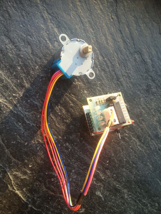
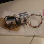
Actually there is no need to explain more about stepper motors than that video does:

Youtube Video

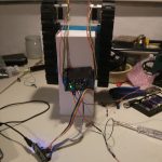
Currently I am using this python code to get the motors running:

#!/usr/bin/env python
 
# import required libs
import time
import RPi.GPIO as GPIO

GPIO.cleanup() #cleaning up in case GPIOS have been preactivated
 
# Use BCM GPIO references
# instead of physical pin numbers
GPIO.setmode(GPIO.BCM)
 
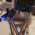
# be sure you are setting pins accordingly
# GPIO10,GPIO9,GPIO11,GPI25
StepPins = [10,9,11,25]
 
# Set all pins as output
for pin in StepPins:
  GPIO.setup(pin,GPIO.OUT)
  GPIO.output(pin, False)

#wait some time to start
time.sleep(0.5)
 
# Define some settings
StepCounter = 0
WaitTime = 0.0015
 
# Define simple sequence
StepCount1 = 4
Seq1 = []
Seq1 = range(0, StepCount1)
Seq1[0] = [1,0,0,0]
Seq1[1] = [0,1,0,0]
Seq1[2] = [0,0,1,0]
Seq1[3] = [0,0,0,1]
 
# Define advanced sequence
# as shown in manufacturers datasheet
StepCount2 = 8
Seq2 = []
Seq2 = range(0, StepCount2)
Seq2[0] = [1,0,0,0]
Seq2[1] = [1,1,0,0]
Seq2[2] = [0,1,0,0]
Seq2[3] = [0,1,1,0]
Seq2[4] = [0,0,1,0]
Seq2[5] = [0,0,1,1]
Seq2[6] = [0,0,0,1]
Seq2[7] = [1,0,0,1]

#Full torque
StepCount3 = 4
Seq3 = []
Seq3 = [3,2,1,0]
Seq3[0] = [0,0,1,1]
Seq3[1] = [1,0,0,1]
Seq3[2] = [1,1,0,0]
Seq3[3] = [0,1,1,0]
 
# set
Seq = Seq2
StepCount = StepCount2
 
# Start main loop
try:
  while 1==1:
    for pin in range(0, 4):
      xpin = StepPins[pin]
      if Seq[StepCounter][pin]!=0:
        #print " Step %i Enable %i" %(StepCounter,xpin)
        GPIO.output(xpin, True)
      else:
        GPIO.output(xpin, False)
    StepCounter += 1

  # If we reach the end of the sequence
  # start again
    if (StepCounter==StepCount):
      StepCounter = 0
    if (StepCounter<0):
      StepCounter = StepCount
 
  # Wait before moving on
    time.sleep(WaitTime)
except:
  GPIO.cleanup();
finally: #cleaning up and setting pins to low again (motors can get hot if you wont) 
  GPIO.cleanup();
  for pin in StepPins:
    GPIO.setup(pin,GPIO.OUT)
    GPIO.output(pin, False)

it is based on code by matt.hawkins but with some improvements I did.

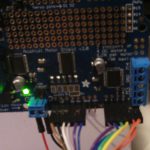
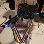
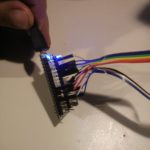
Please be sure you set your GPIOs accordingly to your [amazon &title=Raspberry Pi&text=Raspberry Pi] Revision. So mine was REV 2.0.

Run the code with

sudo python nameOfTheFile.py

and hit [Ctrl]+[C] to stop it. All pins will be set to low afterwards.

In case you want control two motors of this type see another post I made here.


For a different version see:
http://www.intorobotics.com/control-stepper-motors-raspberry-pi-tutorials-resources/http://www.elektronx.de/tutorials/schrittmotorsteuerung-mit-dem-raspberry-pi/