Category Archives: Arduino Micro

Arduino microphone sensor analog + digital

I tried a small arduino microphone recently:

int sensorPin = A0; // select the input pin for the potentiometer
int ledPin = 13; // select the pin for the LED
int sensorValue = 0; // variable to store the value coming from the sensor
 
void setup () 
{
  pinMode (ledPin, OUTPUT);
  Serial.begin (9600);
}
 
void loop () 
{
  sensorValue = analogRead (sensorPin);
  digitalWrite (ledPin, HIGH);
  delay (sensorValue);
  digitalWrite (ledPin, LOW);
  delay (sensorValue);
  Serial.println (sensorValue, DEC);
}

Output looks like that:

22
20
22
22
22
21
22
22
21
22
22
22
22
22
22
22
21
22
22
21


Well explaination how sound sensors work:

Youtube Video

Reset Arduino Micro via python serial

Sometimes resetting a device isn’t as easy as expected. After some research i figured out, that opening a serial connection with a special baud rate would to the job for our Arduino Micro (and similiar like Leonardo):

#!/usr/bin/env python


import serial
port='/dev/ttyACM0' #adjust this in case your device differs
ser = serial.Serial() #open serial connection
ser.port=port #setting the port accordingly

#in case your usual baudrate isn't 9600 reset will not work, therefore we will open a resetable connection
#thanks to mattvenn.net for suggesting to add this step!
ser.baudrate=9600
ser.open(); ser.close()

ser.baudrate=1200 # set the reset baudrate
ser.open(); ser.close()
#don't forget to sleep some reset time

Run the script as root. It might need required to change your port according to your serial controller status.

Arduino Micro and 3.3V IMU LSM9DS0 9DOF

Soldering, Soldering, Soldering 🙂 Everything else had been following the amazingly well written guides of the LSM9DS0 made by sparkfun. Nine degrees of freedom at a rate of “a few per second”(currently 9Hz) since I’ve followed just the basic setup without fancy interrupt usage.

One thing thats really important to mention is the different signal voltage level of the SDA and SCL pins between the Micro(5V) and the IMU Breakout Board(3.3V) – which in case you connect them together without bi-directional level shifting, as you might expect since i2c is designed for exactly that, would lead to blue chip burn.

So wiring on the bread board (and not removing the wires used by the arduino motor shield v2, so do not get too confused by that):

IMG_20140612_192126

and applying the library to the arduino IDE, leads to a working live example with 2 outputs per second:ScreenshotIMULSM9DS0So the next step is to increase the rate by improving the setup wiring, parse that data into ROS Hydro by a SensorMsg/Imu publisher,  kalman and combining these with other odom sources like my currently used (and sadly poor)  or even an GPS source to a exact and really usable Odometry by the robot_pose_ekf package for later Simultaneous Localization and Mapping (SLAM) – a real autonomous mapping and navigation. Sounds easy right?

Arduino Micro and temperature+humidity sensor DHT11

Today is sensor day, so I’ve managed to get the [amazon &title=DHT11&text=DHT11] working:

Wire it like that:
([amazon &title=DHT11&text=DHT11] -> Arduino Micro )

  • Pin 1 (orange cable) to 5V
  • Pin 2 (yellow cable) to GND
  • Pin 3 – not needed
  • Pin 4 (yellow again -.-) to A0

Use the following code I’ve found here:

#include <dht.h>

#define dht_dpin A0 //no ; here. Set equal to channel sensor is on

dht DHT;

void setup(){
  Serial.begin(9600);
  delay(300);//Let system settle
  Serial.println("Humidity and temperaturenn");
  delay(700);//Wait rest of 1000ms recommended delay before
  //accessing sensor
}//end "setup()"

void loop(){
  //This is the "heart" of the program.
  DHT.read11(dht_dpin);

    Serial.print("Current humidity = ");
    Serial.print(DHT.humidity);
    Serial.print("%  ");
    Serial.print("temperature = ");
    Serial.print(DHT.temperature); 
    Serial.println("C  ");
  delay(800);//Don't try to access too frequently... in theory
  //should be once per two seconds, fastest,
  //but seems to work after 0.8 second.
}// end loop()

Getting you a result like that:

It doesn’t seem to be very accurate, but that’s expectable rated by its low price (<2€)


Arduino Micro and barometric pressure sensor BMP180

I’ve experimented with the [amazon &title=BMP180&text=BMP180].  Since its a 3,3V breakout board which is I²C capable I had concerns since the Micro usually uses 5V on its Pins. But without a reason: the I²C on the[amazon &title=BMP180&text=BMP180] needs to get a voltage of 5V and the arduino micro also provides 3.3.
So wiring all together:

Breakout Board -> [amazon &title=Arduino Micro&text=Arduino Micro]
DA -> SDA (Digital 2)
CL -> SCL (Digital 3)
+ -> 3.3 (do NOT plug this to 5V!)
-> GND

Sparkfun offers very good tutorials and source code. The library you’ll need to run this board can be found here

Getting this into your Arduino IDE leads to:

Since its an I²C device it should be stackable with any other I²C device in case they do not have the same BUS-address.


Arduino Micro and temperature sensor LM35

Using the LM35 with the Micro is quite easy.

Just connect:
(LM35 -> [amazon &title=Arduino Micro&text=Arduino Micro] )

  • 5V to positiv
  • GND to
  • S to A4

And run the following code (should run on every arduino):

float temp;
int tempPin = 4;

void setup()
{
  Serial.begin(9600);
}

void loop()
{
  temp = analogRead(tempPin);
  temp = temp * 0.48828125;
  Serial.print("TEMPRATURE = ");
  Serial.print(temp);
  Serial.print("*C");
  Serial.println();
  delay(1000);
}

Getting this result:

Please note its you might need to adjust the 0.48828125 to a value thats verified with another temperature sensor (or just a normal celsius thermometer) .

The next step for me is to write a little ROS publisher for this sensor.


Arduino Micro and Adafruit Motor Shield V2

The Adafruit Motor Shield is a very well documented piece of electronics. Its capable of controlling 2 stepper motors or 4 dc motors with a additional possibility of moving 2 servo motors at once(!). So its perfect for small robot projects!
It has four phases of 1,4 Amps maximum current each with an even higher peak current – in case you cool it for instance by a fan it should even take more regular current like the chips datasheets promise. The voltage of the motors should be between 5 and 12 Volts (can be increased to 13 like most car batteries do have at least as long as I’ve connected it to mine for about 30 minutes).

The coolest thing about it is the I²C protocol (and the connected build in PWM-Chip) it speaks. Because of that its stackable with for instance other motor shields and can drive up to 96 Motors with a single i2c signal giver.
In most cases the signals come from the arduino family, more precisely the Duemilanove, Diecimila, Uno (all revisions), Leonardo and Mega/ADK R3 and higher. As you might recognized, there is no arduino micro in the list, but as it is just a smaller version of the Leonardo it should be possible to work too – right? The answer is: yes it does – at least if you solder right and find the connections that need to be made since the SDA and SCL Pins are digital 2 and 3 on the Micro and A4 and A5 on the shield. Adding 5V, 3V and ground is enough to get it running. (But keep an eye to short circuits and separate powering circuits for the micro)

The i²c protocol (I-squared-C) is supported by the [amazon &title=Raspberry Pi&text=Raspberry Pi] and the [amazon &title=CubieTruck&text=CubieTruck] which means hypothetical it should be possible to run the motor shield with that devices too, but I would not recommend to do so, as there is nearly no code library at the time of this post beeing written.

The motor shield comes with an arduino library where everything gets explained very well. Just one thing they forget to mention is the needed:

#define USE_USBCON

the motors
I’ve got to admit that the motors had been a bad joice so far – they are way to weak. I nearly drove me nuts to get them working, because I couldn’t believe how weak they are 🙂
So I’ve learned a lot about stepper motors datasheets and all of its very confusing unit handling the hard way. And I’ve done the mistake a lot of stepper motor newbies do: assuming the voltage needs to be the same as the batteries voltage. Avoid that thought in case you are building a robot currently 🙂

Arduino Micro /Leonardo and rosserial Hello World possible link problem?

Yesterday I’ve had to learn something the hard way. Please have a look at the following code of the rosserial “hello world” arduino example:

/*
 * rosserial Publisher Example
 * Prints "hello world!"
 */

#include <ros.h>
#include <std_msgs/String.h>

ros::NodeHandle  nh;

std_msgs::String str_msg;
ros::Publisher chatter("chatter", &str_msg);

char hello[13] = "hello world!";

void setup()
{
  nh.initNode();
  nh.advertise(chatter);
}

void loop()
{
  str_msg.data = hello;
  chatter.publish( &str_msg );
  nh.spinOnce();
  delay(1000);
}

Nothing special, right? So compiling it – uploading everything on the arduino works like a charm.

But starting it  rosrun rosserial_python serial_node.py /dev/ttyACM0 crashes with:

rosrun rosserial_python serial_node.py /dev/ttyACM0
[INFO] [WallTime: 1400737593.278250] ROS Serial Python Node
[INFO] [WallTime: 1400737595.610358] Connecting to /dev/ttyACM0 at 57600 baud
/home/yourUser/catkin_ws/src/rosserial/rosserial_python/src/rosserial_python/SerialClient.py:317: SyntaxWarning: The publisher should be created with an explicit keyword argument 'queue_size'. Please see http://wiki.ros.org/rospy/Overview/Publishers%20and%20Subscribers for more information.
  self.pub_diagnostics = rospy.Publisher('/diagnostics', diagnostic_msgs.msg.DiagnosticArray)
[ERROR] [WallTime: 1400737595.826375] Error opening serial: could not open port /dev/ttyACM0: [Errno 13] Permission denied: '/dev/ttyACM0'

which can be easily explained by normal users missing permission to access the /dev/ttyACM0. So I advice running it as root, which leads you to customize roots .bashrc including the source /home/yourUser/yourWorkspacePath/devel/setup.bash and the environment variables like ROS_HOSTNAME and ROS_MASTER.

So after that, running it again with root permissions, you’ll get another error message:

[INFO] [WallTime: 1400737809.741920] ROS Serial Python Node
[INFO] [WallTime: 1400737810.415142] Connecting to /dev/ttyACM0 at 57600 baud
/home/yourUser/catkin_ws/src/rosserial/rosserial_python/src/rosserial_python/SerialClient.py:317: SyntaxWarning: The publisher should be created with an explicit keyword argument 'queue_size'. Please see http://wiki.ros.org/rospy/Overview/Publishers%20and%20Subscribers for more information.
  self.pub_diagnostics = rospy.Publisher('/diagnostics', diagnostic_msgs.msg.DiagnosticArray)
[ERROR] [WallTime: 1400737827.716961] Unable to sync with device; possible link problem or link software version mismatch such as hydro rosserial_python with groovy Arduino

So – rosserial tries to connect to your /dev/ttyACM0 using 57600 baud and fails. The error message is kind of misleading – of course there is some syncing issue, and it has nothing to do with your ROS version… …but with your arduino!

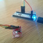
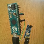
Since the arduino micro / leonardo uses USB for and its build in serial-controller both for programming and communicating, rosserial needs the information to access the device not in the for arduino usual serial way but with USB. So simply adding

#define USE_USBCON

before the rest of the code, will tell ROS to do so.


Ultrasonic Sensor HC-SR04 as a ROS Range publisher

I’ve taken a HC-SR04 like shown below and connected it to the CubieTruck as a rosserial publisher.

IMG_20140512_114741


Instead a of a simple std_msgs::String str_msg;  I’ve implemented a sensor_msgs::Range range_msg; which after starting the arduino in ros with rosrun rosserial_python serial_node.py /dev/ttyACM0  shows up in rostopic echo /ultrasound like this:

---
header: 
  seq: 136
  stamp: 
    secs: 1400706588
    nsecs: 709593997
  frame_id: ultrasound
radiation_type: 0
field_of_view: 0.10000000149
min_range: 0.0
max_range: 4.0
range: 1.18762886524
---

So with that, its possible to visualize everything using rqt_plot:

ScreenshotROSUltraSound

which is pretty nice for my first arduino micro ros project and less than an two hours of work 🙂

For further information see here


Howto run a 12V bipolar stepper motor with arduino micro and L298N at 150rpm

Today I experimented with a 12V bipolar stepper motor and the 5V arduino micro.

To get things working I’ve put the 9V from my six 1.5V Batteries into an UBEC which accelerates them to 12V at a loss of below 10% (at 350mAh) connected them to the VCC of the L298N and wired the 4 signal cables of the motors to it. Because thats a lot of numbers to keep track of – I’ve made a small video of the setup:

Youtube Video

Doing the math according to a wheel with 5,8cm heigth and 150rpm I’ve reached, my robot will be able to run about 1,6 km/h – this might be increased with a better motor driver like they used on the arduino motor shield. I’ve read they reached about 250 rpm on the same motor which would be 2,73km/h.

The code of the arduino is pretty simple:

#include <Stepper.h>

const int stepsPerRevolution = 200;  // change this to fit the number of steps per revolution
// for your motor


// init the stepper lib on pins 8 through 11:
Stepper myStepper(stepsPerRevolution, 8,9,10,11);            

void setup() {
  // nothing to do inside the setup
}

void loop() {
    myStepper.setSpeed(150);
    myStepper.step(stepsPerRevolution/100); 
}