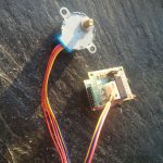
For low cost robots, remote controlled laser pointers, cat or fish feeding machines I found a really cheap way to move things by programmable wifi. The already handy usable 28BYJ-48 coming small motor driver i board is available in china for about 2$. It additionally needs to be driven by a fast micro controller like the Arduino or the much more capable Raspberry Pi. As I was experimenting with the esp2866 12-Q recently, the combination of this two useful things seemed more than obvious. Therefore I decided to give it a try.
Unfortunately the stepper motor and its driver chip the ULN2003a need at least 5Vs to run, a voltage the esp2866 would by killed by as its maximum rating is about 3.6. in conclusion two power circuits or two power sources would be required. I tried to keep things simple by using an 5V-12V power source and step down converting it to 3.3V with an lm2655 based step down circuit. This setup allows an efficiency about 95% and avoids producing high amounts of heat as linear step down converters would have done. Overall the motor and the controllers consume 0.35 Amps at 5V therefore about 1.75 Watts.
-
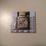
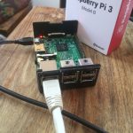
- 28BYI-48 stepper motor with Wifi – esp2866 on breadboard adapter
-
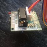
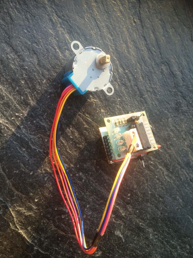
- 28BYI-48 stepper motor with Wifi ULN2003a driver board
-
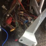
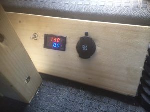
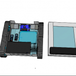
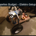
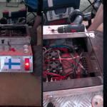
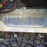
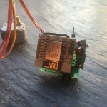
- 28BYI-48 stepper motor with Wifi – final setup
-
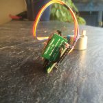
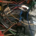
- 28BYI-48 stepper motor with Wifi -final setup 2
-
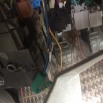
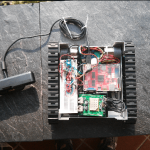
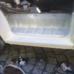
- 28BYI-48 stepper motor with Wifi – final setup 3
-
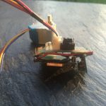
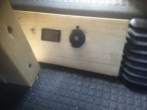
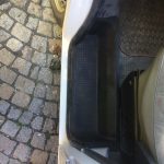
- 28BYI-48 stepper motor with Wifi – final setup 4
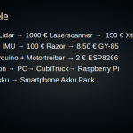
Parts
- 2$ 28BYJ-48 with ULN2003a motor driver
- 2$ esp8266
- 2$ step-down-converter
- > 0,5$ breadboard 2.5 mm adapter for the esp8266
- > 0,.5$ for15 cm of additional cables low diameter
- soldering equipment and an 3.3V FTDI Adapter for flashing the esp2866
Steps to build your own:
- solder the esp2866 on the adapter board
- reverse the in1 in2 in3 in4 pins to the other side of the motor driver ULN2003a board
- put the breadboard adapter on this pins starting with vcc followed by in1 to in4
- connect the v_out of the step down circuit with vcc of the breadboard adapter
- connect v_in of the step down circuit to the vcc of the motor driver board
- connect all GNDs together
- add pins on the breadboard adapter for flasingh the esp2866, GND, VCC, TX and RX
- flash the esp2866 with
https://github.com/PaulPetring/esp2866-28BYJ-48-motor-control/blob/master/simple.ino - test solderinng and apply between 5V an 12V connected to the motor driver board
- have fun 🙂
Wiring concept
https://github.com/PaulPetring/esp2866-28BYJ-48-motor-control