Unpacking
The M3D printer is the result of a successfull kickstarter campaign where 11.855 founders backed 3.401.361 $ USD. I came across this beautiful little device at the Chemnitzer Linux Tage 2016 and somehow fell in love. I immediately ordered the device from the companies website printm3d.com, which was possible because the company started selling various models shortly before. Having the choice I’ve ordered a crystal clear case with 349 $ USD + 25 $ USD fee for beeing clear, 49 $ USD for packaging and worldwide express shipping.
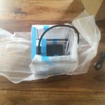
Only a few days later a little package arrived at my door, held by an UPS delivery guy asking for an additional VAG of about 80 € EUR. Which I expected, but never was prepared for by the manufacturer.Overall in germany the printer not as cheap as promoted everywhere, but still unpackaging was really pleasant:
-
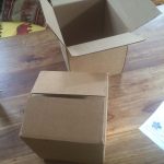
- The M3D – box in a box
-
- The M3D – main box bottom
-
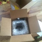
- The M3D – opening the inner box
-
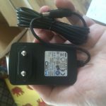
- The M3D – power adapter
-
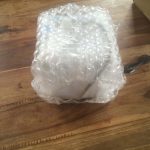
- The M3D – bubble wrap
-
- The M3D – freeing the printer
-
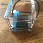
- The M3D – with blue securing tape and holding clips
-
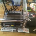
- The M3D – on my laptop
-
- The M3D – close up
I’ve taken this pictures a while ago, nowadays there are nice videos of the unpacking process I highly recomment:
Software
Beside the price, there are other pros and cons of the printer. First of all its software is genius and catastrophic at the same time. From a beginners point of view having a nice catchy windows application which runs on the latest plattform and service pack is perfect. But having no Linux interface, no reliable instructions for setting it up a working setup is nothing M3D should be proud of. It took me several days to connect the printer to my virtual box windows emulation environment. It never worked stable and embarrassed me and my enthusiasm in front of friends I wanted to show the little magic cube.
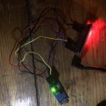
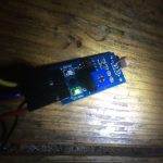
Nevertheless, there is hope! A nice plugin called M3D-Fio for multi-printer software Octoprint. It can be installed on a simple Raspberry Pi and offers a website where you are able to upload .stl files, slice them to the m3d gcode by using the ultimaker slicing software called Cura, and flash the current M3D firmware. Only by that, the printer is usable to me. And it has the nice side effect of beeing able to leave the room taking my laptop with me, and saving a lot of energy by not beeing required to run a dedicated windows machine while printing.

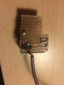
My Octoprint setup.
For the sake of completeness:I can’t evaluate the MacOS Version of the software, because I do not use an apple laptop.

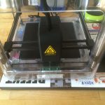
M3D – while printing
Overall i can say, the M3D i brought was really worth it.