Category Archives: Howtos

Check if NetworkManager is running on Ubuntu / Debian

Usually you should be using NetworkManager by default (Ubuntu 14.04), just in case you want to be sure, use this command to verify:

dpkg --get-selections | grep network-manager

In case there is some output like:

network-manager					install

it is installed, if there is nothing returned, you are probably using a different network managing daemon.

It would be possible that network manager is installed but inactive. Lets check if its running the hard way:

ps aux | grep network-manager

If thats returning something different than itself, you can be sure using the NetworkManager in Ubuntu / Debian.

Save a list of installed packages on Ubuntu / Debian

In case your laptop crashes during your thesis writing it would be nice to have a list of which packets have been installed.

In Ubuntu / Debian or other some other distros there is a tool called dkpg which offers a small command that can be very helpful:

dpkg --get-selections | grep -v deinstall

Saving that list in your backup routine (e.g. of your /home/ dir) every hour using crontab (linux scheduled tasks)

crontab -e
#follow the dialog and add this line to your crontab
0 1 * * * dpkg --get-selections | grep -v deinstall > ~/packages.txt

Arduino Micro and temperature+humidity sensor DHT11

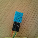
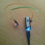
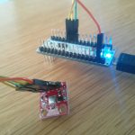
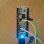
Today is sensor day, so I’ve managed to get the [amazon &title=DHT11&text=DHT11] working:

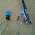
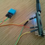
Wire it like that:
([amazon &title=DHT11&text=DHT11] -> Arduino Micro )

  • Pin 1 (orange cable) to 5V
  • Pin 2 (yellow cable) to GND
  • Pin 3 – not needed
  • Pin 4 (yellow again -.-) to A0

Use the following code I’ve found here:

#include <dht.h>

#define dht_dpin A0 //no ; here. Set equal to channel sensor is on

dht DHT;

void setup(){
  Serial.begin(9600);
  delay(300);//Let system settle
  Serial.println("Humidity and temperaturenn");
  delay(700);//Wait rest of 1000ms recommended delay before
  //accessing sensor
}//end "setup()"

void loop(){
  //This is the "heart" of the program.
  DHT.read11(dht_dpin);

    Serial.print("Current humidity = ");
    Serial.print(DHT.humidity);
    Serial.print("%  ");
    Serial.print("temperature = ");
    Serial.print(DHT.temperature); 
    Serial.println("C  ");
  delay(800);//Don't try to access too frequently... in theory
  //should be once per two seconds, fastest,
  //but seems to work after 0.8 second.
}// end loop()

Getting you a result like that:

It doesn’t seem to be very accurate, but that’s expectable rated by its low price (<2€)


Arduino Micro and barometric pressure sensor BMP180

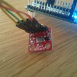
I’ve experimented with the [amazon &title=BMP180&text=BMP180].  Since its a 3,3V breakout board which is I²C capable I had concerns since the Micro usually uses 5V on its Pins. But without a reason: the I²C on the[amazon &title=BMP180&text=BMP180] needs to get a voltage of 5V and the arduino micro also provides 3.3.
So wiring all together:

Breakout Board -> [amazon &title=Arduino Micro&text=Arduino Micro]
DA -> SDA (Digital 2)
CL -> SCL (Digital 3)
+ -> 3.3 (do NOT plug this to 5V!)
-> GND

Sparkfun offers very good tutorials and source code. The library you’ll need to run this board can be found here

Getting this into your Arduino IDE leads to:

Since its an I²C device it should be stackable with any other I²C device in case they do not have the same BUS-address.


Arduino Micro and temperature sensor LM35

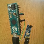
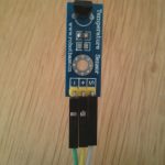
Using the LM35 with the Micro is quite easy.

Just connect:
(LM35 -> [amazon &title=Arduino Micro&text=Arduino Micro] )

  • 5V to positiv
  • GND to
  • S to A4

And run the following code (should run on every arduino):

float temp;
int tempPin = 4;

void setup()
{
  Serial.begin(9600);
}

void loop()
{
  temp = analogRead(tempPin);
  temp = temp * 0.48828125;
  Serial.print("TEMPRATURE = ");
  Serial.print(temp);
  Serial.print("*C");
  Serial.println();
  delay(1000);
}

Getting this result:

Please note its you might need to adjust the 0.48828125 to a value thats verified with another temperature sensor (or just a normal celsius thermometer) .

The next step for me is to write a little ROS publisher for this sensor.


ROS Hydro / Indigo PointCloud to Laserscan for 2D Navigation

UPDATE: see my step by step guide for depthimage_to_laserscan here.

PointClouds need a lot of processing and network traffic load. For 2D navigation LaserScans are a good option to decrease this loads, in my case below to 30% of the original.

So after starting my customized openni2_launch (the launchers of openni_camera, and both ros drivers) with a custom Openni2 driver dir:

OPENNI2_DRIVERS_PATH=/usr/lib/OpenNI2/Drivers/ roslaunch /home/user/catkin_ws/src/robot_bringup/launch/openni2.launch

(OPENNI2_DRIVERS_PATH fixes all issues with the camera driver nodelet)

its possible to process this down to a /scan topic by:

rosrun depthimage_to_laserscan depthimage_to_laserscan image:=/camera/depth/image_raw

or directly in a launch file using the handy nodelet manager:

  <group>
    <node pkg="nodelet" type="nodelet" name="depthimage_to_laserscan" args="load depthimage_to_laserscan/DepthImageToLaserScanNodelet $(arg camera)/$(arg camera)_nodelet_manager">
      <param name="scan_height" value="10"/>
      <param name="output_frame_id" value="/$(arg camera)_depth_frame"/>
      <param name="range_min" value="0.45"/>
      <remap from="image" to="$(arg camera)/$(arg depth)/image_raw"/>
      <remap from="scan" to="$(arg scan_topic)"/>

      <remap from="$(arg camera)/image" to="$(arg camera)/$(arg depth)/image_raw"/>
      <remap from="$(arg camera)/scan" to="$(arg scan_topic)"/>
    </node>
  </group>

After that it is possible to visualize the new topic using rviz getting something like that:

of course the robot is still able to laserscan with the xtion (now in rainbow indicating z of the camera)


Set vim filetype by its file extension

For my project I am constantly edition ROS .launch files, which are some kind of xml.

If I want to use syntax highlighting for better readability, I used to type :set filetype=xml . Which works, but gets kinda annoying in case you’ve got to type it multiple times a day.

In case you want to open .launch files with xml syntax by default, create a file in your .vim-folder:

mkdir $HOME/.vim/ #create the folder in case it doesn't exist yet
vim $HOME/.vim/filetype.vim #open it in vim

Change into insert mode (press i) and paste following code into it:

if exists("did_load_filetypes")
  finish
endif
augroup filetypedetect
  au! BufNewFile,BufRead *.launch setf xml
augroup END

Thats’s it, after that your vim will change:

before and default

before and default

after edits or set filetype=xml

after edits or set filetype=xml

Arduino Micro /Leonardo and rosserial Hello World possible link problem?

Yesterday I’ve had to learn something the hard way. Please have a look at the following code of the rosserial “hello world” arduino example:

/*
 * rosserial Publisher Example
 * Prints "hello world!"
 */

#include <ros.h>
#include <std_msgs/String.h>

ros::NodeHandle  nh;

std_msgs::String str_msg;
ros::Publisher chatter("chatter", &str_msg);

char hello[13] = "hello world!";

void setup()
{
  nh.initNode();
  nh.advertise(chatter);
}

void loop()
{
  str_msg.data = hello;
  chatter.publish( &str_msg );
  nh.spinOnce();
  delay(1000);
}

Nothing special, right? So compiling it – uploading everything on the arduino works like a charm.

But starting it  rosrun rosserial_python serial_node.py /dev/ttyACM0 crashes with:

rosrun rosserial_python serial_node.py /dev/ttyACM0
[INFO] [WallTime: 1400737593.278250] ROS Serial Python Node
[INFO] [WallTime: 1400737595.610358] Connecting to /dev/ttyACM0 at 57600 baud
/home/yourUser/catkin_ws/src/rosserial/rosserial_python/src/rosserial_python/SerialClient.py:317: SyntaxWarning: The publisher should be created with an explicit keyword argument 'queue_size'. Please see http://wiki.ros.org/rospy/Overview/Publishers%20and%20Subscribers for more information.
  self.pub_diagnostics = rospy.Publisher('/diagnostics', diagnostic_msgs.msg.DiagnosticArray)
[ERROR] [WallTime: 1400737595.826375] Error opening serial: could not open port /dev/ttyACM0: [Errno 13] Permission denied: '/dev/ttyACM0'

which can be easily explained by normal users missing permission to access the /dev/ttyACM0. So I advice running it as root, which leads you to customize roots .bashrc including the source /home/yourUser/yourWorkspacePath/devel/setup.bash and the environment variables like ROS_HOSTNAME and ROS_MASTER.

So after that, running it again with root permissions, you’ll get another error message:

[INFO] [WallTime: 1400737809.741920] ROS Serial Python Node
[INFO] [WallTime: 1400737810.415142] Connecting to /dev/ttyACM0 at 57600 baud
/home/yourUser/catkin_ws/src/rosserial/rosserial_python/src/rosserial_python/SerialClient.py:317: SyntaxWarning: The publisher should be created with an explicit keyword argument 'queue_size'. Please see http://wiki.ros.org/rospy/Overview/Publishers%20and%20Subscribers for more information.
  self.pub_diagnostics = rospy.Publisher('/diagnostics', diagnostic_msgs.msg.DiagnosticArray)
[ERROR] [WallTime: 1400737827.716961] Unable to sync with device; possible link problem or link software version mismatch such as hydro rosserial_python with groovy Arduino

So – rosserial tries to connect to your /dev/ttyACM0 using 57600 baud and fails. The error message is kind of misleading – of course there is some syncing issue, and it has nothing to do with your ROS version… …but with your arduino!

Since the arduino micro / leonardo uses USB for and its build in serial-controller both for programming and communicating, rosserial needs the information to access the device not in the for arduino usual serial way but with USB. So simply adding

#define USE_USBCON

before the rest of the code, will tell ROS to do so.


Howto use CubieTruck and NetworkManager to do WPA2 Enterprise TLS

Last days the [amazon &title=CubieTruck&text=CubieTruck] made me struggle with its Network behavior. It continuously refused to connect to any WLAN, didn’t allow the Usage of the NetworkManager GUI, and confused me a lot.

Some things that might help you:

Wlan isn’t enabled by default – or at least it wasn’t for me.

Load the driver

modprobe bcmdhd

In case you don’t want to do that everytime the [amazon &title=CubieTruck&text=CubieTruck] needs wifi consider adding a new line with ‘bcmdhd’ (no quotes) to /etc/modules

I needed to install the linux firmware:

sudo apt-get install linux-firmware -y

and reboot

sudo reboot

3. bring the wlan0 device up and scan if your wlan is available

sudo -i #get root 
ifconfig wlan0 up
iwlist wlan0 scan

Check if the /etc/network/interfaces file looks something like that:

auto lo eth0
iface lo inet loopback

No additional lines, or the NetworkManager will struggle with your devices, showing them as “not managed” or “disconnected”.

So by default lubuntu 13.04 image, no Network manager has been running by boot, so I’ve fixed that by adding following line to my /etc/crontab:

@reboot /usr/sbin/NetworkManager

(sure there are other ways – especially because it’s a system service)

So after reboot – using the [amazon &title=CubieTruck&text=CubieTruck]-GUI its faces you with a “Network Manager not running”.

Screenshot[amazon &title=CubieTruck&text=CubieTruck]

So the small Icon on the taskbar isn’t able to find the network manager.
I could not fix that other than by opening an LXTerminal and:

sudo killall nm-applet && sudo nm-applet

which leads me to a nice WLAN GUI and made it possible to use WPA2 Enterprise with TLS 🙂

Howto control CubieTruck onboard LEDs

Today I wanted to know, what this little blinking lights on my [amazon &title=CubieTruck&text=CubieTruck] mean.

There are four, which you find out if you use:

root@cubietruck:/# ls /sys/class/leds/

blue:ph21:led1 green:ph07:led4 orange:ph20:led2 white:ph11:led3

(or just look at it while it is running, usually it blinks a lot)

IMG_20140520_123004

So if you want to know what each blink means you can ask the [amazon &title=CubieTruck&text=CubieTruck] like that:

root@cubietruck:cd /sys/class/leds/
root@cubietruck:/sys/class/leds# ls
blue:ph21:led1  green:ph07:led4  orange:ph20:led2  white:ph11:led3
root@cubietruck:/sys/class/leds# cat green:ph07:led4/trigger
none rfkill0 battery-charging-or-full battery-charging battery-full battery-charging-blink-full-solid ac-online usb-online [mmc0] mmc1 timer heartbeat cpu0 cpu1 default-on rfkill1 rfkill2 
root@cubietruck:/sys/class/leds# cat blue:ph21:led1/trigger
none rfkill0 battery-charging-or-full battery-charging battery-full battery-charging-blink-full-solid ac-online usb-online mmc0 mmc1 timer [heartbeat] cpu0 cpu1 default-on rfkill1 rfkill2 
root@cubietruck:/sys/class/leds# cat orange:ph20:led2/trigger
none rfkill0 battery-charging-or-full battery-charging battery-full battery-charging-blink-full-solid ac-online usb-online mmc0 mmc1 timer heartbeat [cpu0] cpu1 default-on rfkill1 rfkill2 
root@cubietruck:/sys/class/leds# cat white:ph11:led3/trigger
none rfkill0 battery-charging-or-full battery-charging battery-full battery-charging-blink-full-solid ac-online usb-online mmc0 mmc1 timer heartbeat cpu0 [cpu1] default-on rfkill1 rfkill2 

So by default the

  • green LED is indicating if there is any read write with the SD Card
  • blue LED is heartbeating
  • orange LED is CPU0 load
  • white LED is CPU1 load

In case you want to turn off the LEDS, use this code:

# turn off LEDs
echo 0 > /sys/class/leds/blue:ph21:led1/brightness
echo 0 > /sys/class/leds/green:ph07:led4/brightness
echo 0 > /sys/class/leds/white:ph11:led3/brightness
echo 0 > /sys/class/leds/orange:ph20:led2/brightness

See here for more information.