


It sure is. But a good odometry in a robotic context is an objective that is hard to achieve. For a robot like the aMoSeRo only two main velocities are relevant: linear and angular speed. Both do not occur on the same time, but still – correctly determining any of them is essential as most higher algorithms like slamming and planning highly depend on it. For me in a out of time running thesis, this task can be the biggest still kinda opened challenge.
All other system parts like gmapping, robot_pose_ekf, tf_broadcasts, sensor code, drivers, dynamic_reconfigure (insert long list of other important things here) are up and well enough running. Most of the thesis is written, only evaluation (experiments) and conclusion (the big round up in the end) is still missing.
Therefore I am really looking forward to a time after my thesis – full of well deserved sleep and a university degree 🙂

So before trying to get the planned stepper motors running, I quickly put a dc motors setup together:
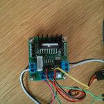
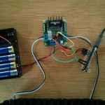
I’ve got two dc motors coming with my make block robot starter kit. And for research I also ordered a small l298n motor controller shield which is able to control motors up to 24Vs and 2A each by 4 small input wires at for example 3,3V and 2 additional +5V motor enablers.
There is a nice little page which explains all states of the L298N according to the arduino micro here. For a [amazon &title=Raspberry Pi&text=Raspberry Pi] I found a nice Youtube video explaining everything here.
For me in the end both motors rotated quite nicely, like this video shows:
For the micro I wrote this peace of code:
const int IN1 = 10;
const int IN2 = 11;
const int IN3 = 8;
const int IN4 = 9;

void setup()
{
  pinMode(IN1, OUTPUT);
  pinMode(IN2, OUTPUT);
  pinMode(IN3, OUTPUT);
  pinMode(IN4, OUTPUT);
}

void loop()
{
  digitalWrite(IN1, HIGH);
  digitalWrite(IN2, LOW);
  digitalWrite(IN3, HIGH);
  digitalWrite(IN4, LOW);

  //hold speed fro 5 seconds
  for(byte j = 5; j > 0; j--)
  {
    delay(1000);
  }

  //stop for two seconds.
  digitalWrite(IN1, LOW);
  digitalWrite(IN2, LOW);
  digitalWrite(IN3, LOW);
  digitalWrite(IN4, LOW);
  delay(2000);

  //switching direction
  digitalWrite(IN1, LOW);
  digitalWrite(IN2, HIGH);
  digitalWrite(IN3, LOW);
  digitalWrite(IN4, HIGH);


 //hold speed for 5 seconds
 for(byte u = 5; u > 0; u--)
  {
    delay(1000);
  }
}
This is my very first arduino application. But its simple and amazing.
You will need 4 female to female jumper wires and [amazon &title=HC-SR04&text=HC-SR04] ultrasonic sensor, a microusb cable and in the end you’ll be able to measure distances with this little device.
Just wire it like shown below:

I used pins 7 (orange echo) and 8 (yellow trigger) for data pins, 5V(red) and ground(black).
I have taken some code from this page. The result you can see in the screenshot below, its a amount of cm written in the serial console:

/*
 [amazon &title=HC-SR04&text=HC-SR04] Ping distance sensor:
 VCC to arduino 5v
 GND to arduino GND
 Echo to Arduino pin 7
 Trig to Arduino pin 8

 This sketch originates from Virtualmix: http://goo.gl/kJ8Gl
 Has been modified by Winkle ink here: http://winkleink.blogspot.com.au/2012/05/arduino-hc-sr04-ultrasonic-distance.html
 And modified further by ScottC here: http://arduinobasics.blogspot.com.au/2012/11/arduinobasics-hc-sr04-ultrasonic-sensor.html
 on 10 Nov 2012.
 */


#define echoPin 7 // Echo Pin
#define trigPin 8 // Trigger Pin
#define LEDPin 13 // Onboard LED

int maximumRange = 200; // Maximum range needed
int minimumRange = 0; // Minimum range needed
long duration, distance; // Duration used to calculate distance

void setup() {
 Serial.begin (9600);
 pinMode(trigPin, OUTPUT);
 pinMode(echoPin, INPUT);
 pinMode(LEDPin, OUTPUT); // Use LED indicator (if required)
}

void loop() {
/* The following trigPin/echoPin cycle is used to determine the
 distance of the nearest object by bouncing soundwaves off of it. */
 digitalWrite(trigPin, LOW);
 delayMicroseconds(2);

 digitalWrite(trigPin, HIGH);
 delayMicroseconds(10);

 digitalWrite(trigPin, LOW);
 duration = pulseIn(echoPin, HIGH);

 //Calculate the distance (in cm) based on the speed of sound.
 distance = duration/58.2;

 if (distance >= maximumRange || distance <= minimumRange){
 /* Send a negative number to computer and Turn LED ON
 to indicate "out of range" */
 Serial.println("-1");
 digitalWrite(LEDPin, HIGH);
 }
 else {
 /* Send the distance to the computer using Serial protocol, and
 turn LED OFF to indicate successful reading. */
 Serial.println(distance);
 digitalWrite(LEDPin, LOW);
 }

 //Delay 50ms before next reading.
 delay(50);
}
Before I dismantle my little [amazon &title=Raspberry Pi&text=Raspberry Pi] Robot #1 , I wanted to have a little video of its base_controller working together with the turtlebot teleop. It uses the geometry/Twist messages to transmit moving information like a lot of ROS Robots do.
As you see there is a little acceleration control implemented which makes the robot start smoothly and stop after gently after no key is pressed anymore. In case of emergency its possible to hit e.g. the space bar for a instant full stop.
This robot isn’t very fast – but the next one will be. So this was a successful ROS-learning robot which I can recommend to everyone who wants to know how ROS Robots work.
Its a bit hard to get all of the source compiled on the small arm cpu, and there are nearly no precompiled packages – but it takes away all the fear from compiling errors in the future 🙂
Today the new parts arrived, which is why there will be a lot of new posts soon.
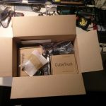
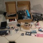
There is a [amazon &title=CubieTruck&text=CubieTruck] in it, better stepper motors, a lot of sensors, tracks and wheels – so a lot of work in a box 🙂
That’s one small step for a man, one giant leap for a small raspberry powered ROS robot.
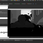
Okay – maybe thats a bit too big – but I am in a good mood. I compiled the latest openni2_camera ros driver on the little arm cpu of the [amazon asin=B00LPESRUK&text=[amazon &title=Raspberry Pi&text=Raspberry Pi]]. Before that, I used the driver provided by kalectro (see source), which is an older fork but prepared for raspberry.
As a result of that, I’ve got some new features like the IR-Image stream I visualized with rviz :

Raspberry Pi Robot with ROS
or the handy little parameter with which it is possible to skip some frames which reduces the load a bit:
set param name="camera/driver/data_skip" value="300"
rosrun openni2_camera openni2_camera_node
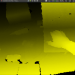
Now, running roscore on my laptop – I had some sensor_msg/Images I needed to convert into 3d depth data. After some little issues with faulty XML-launch files, I finally got openni2_launch up and running, which is a handy little launchfile using rgb_launch providing every data format you’ll can get out of the [amazon &title=Xtion&text=Asus Xtion].
roslaunch openni2_camera openni2.launch
Now I’ve had a /camera/depth/points topic, with a pointcloud2 datatype. Which is really nice because rviz can visualize it:

Raspberry Pi Robot with ROS – Xtion
Houston, we’ve had a problem.
Yes, there were times when it was possible to land on the moon by the power of a daily life calculator – but todays robots need more than that 🙂 So my aged Intel Centrino Core 2 Duo ASUS-F3J with 1,7Ghz each core isn’t able to do more than I reached today. It pops to 100% processing and after some time it collapses totally.
So todays lesson learned is:
Robots are distributed systems – by every measure.
So I’ll need more power.. again…
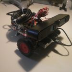
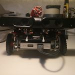
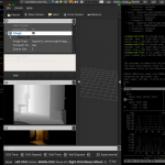
I’ve completed a new version today. It is a bit smaller and heavier, but already running ros hydro (I will write a small tutorial soon how to achieve that) with OpenNI2 and the ros-package openni2-camera. With that its possible to stream data to another computer visualizing the depth image of the [amazon &title=Asus Xtion&text=Asus Xtion] in rviz. I had some trouble solving and compiling all drivers, dependencies like ros-packages and libs like openCV (see Howto).
When the camera node is running the Raspberry is faced at with a processing load of 100%. The used network bandwidth is about 200-300 kb/s.
I suppose the raspberry Pi needs to be replaced by something stronger soon.
But for my first week in robotics, it’s something 🙂
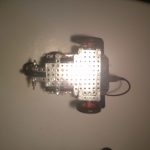
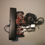
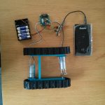
I am trying to build my own [amazon &title=Raspberry Pi&text=Raspberry Pi] based robot. Someday, it shall be able to drive autonomously based on data from its [amazon &title=Asus Xtion&text=Asus Xtion] (a smaller version of an Xbox Kinect) and with the help of ROS (Robot Operating System). For today, it is only capable of driving straight forward.

Parts:
With this setup, the raspberry i able to run at least 8 hours by the power of my already a little bit aged powerbank. Driving at an unbelievable slow speed of about 30 seconds per meter (full torque mode of steppers).
For documentation (and for fun, because I never did this before), here a small video of the very first test drive: