Tag Archives: ROS Hydro

ROS Hydro/Indigo and sparkfun IMU LSM9DS0 9DOF

I’ve connected the LSM9DS0 9 degrees of Freedom Breakout Board made by sparkfun with an arduino micro like I’ve described in a previous post, wrote a little rosserial sensor_msgs::Imu publisher and visualized everything using the rqt plugin manager for further experimenting.

Here a screenshot while moving the setup:

ScreenshotIMURos

a screenshot while not touching:

ScreenshotIMURos2

As you see all data is still moving a lot. So the next step beside finding out what the units really mean, will be stabilizing by using a kalman filter like its provided in the robot_pose_ekf package.

By the way: the arduino is currently using around 25000 of its 28 672 bytes memory just providing the IMU data to ros. So the motorshield will require another micro or we switch it to something else like an wiimote.

ROS Transformation and Odometry based on URDF Convention REP103

In order to get ROS working correctly, you need a lot things to be set up according to ROS defined conventions: for instance the ‘Standard Units of Measure and Coordinate Conventions’ (REP103), which clearly explains which units geometry_msgs.Twist should have or in what movement direction your robot need to be inside its URDF file.

For me this meant to redo my xacro (URDF-Macro) defined robot driving direction and its according tf-links. Since I’ve already gained some experience in creating robot models I tried to improve it a bit too:

I will explain the robots hardware setup in another post as soon as its possible to run it by keyboard teleop while publishing its accurate odometry. Odometry Messages aren’t simply ROS transformations like moving parts of the robot. Because the robot belongs to the physical world where for example friction exists and further wheel jamming could happen, all the calculated position data need to by verified. Qualified for this task is sensor data like Ultrasonic Sensor Ranges, motor potentiometer or stepper motor positions or Openni2 data provided by the [amazon &title=Xtion&text=Asus Xtion]. After publishing this Odometry messages to the /odom topic, the ros navigation packages can generate geometry/Twist messages to correct the position to mach the simulation again in case there has been some deviation.

More on this topic soon.

ROS Hydro / Indigo PointCloud to Laserscan for 2D Navigation

UPDATE: see my step by step guide for depthimage_to_laserscan here.

PointClouds need a lot of processing and network traffic load. For 2D navigation LaserScans are a good option to decrease this loads, in my case below to 30% of the original.

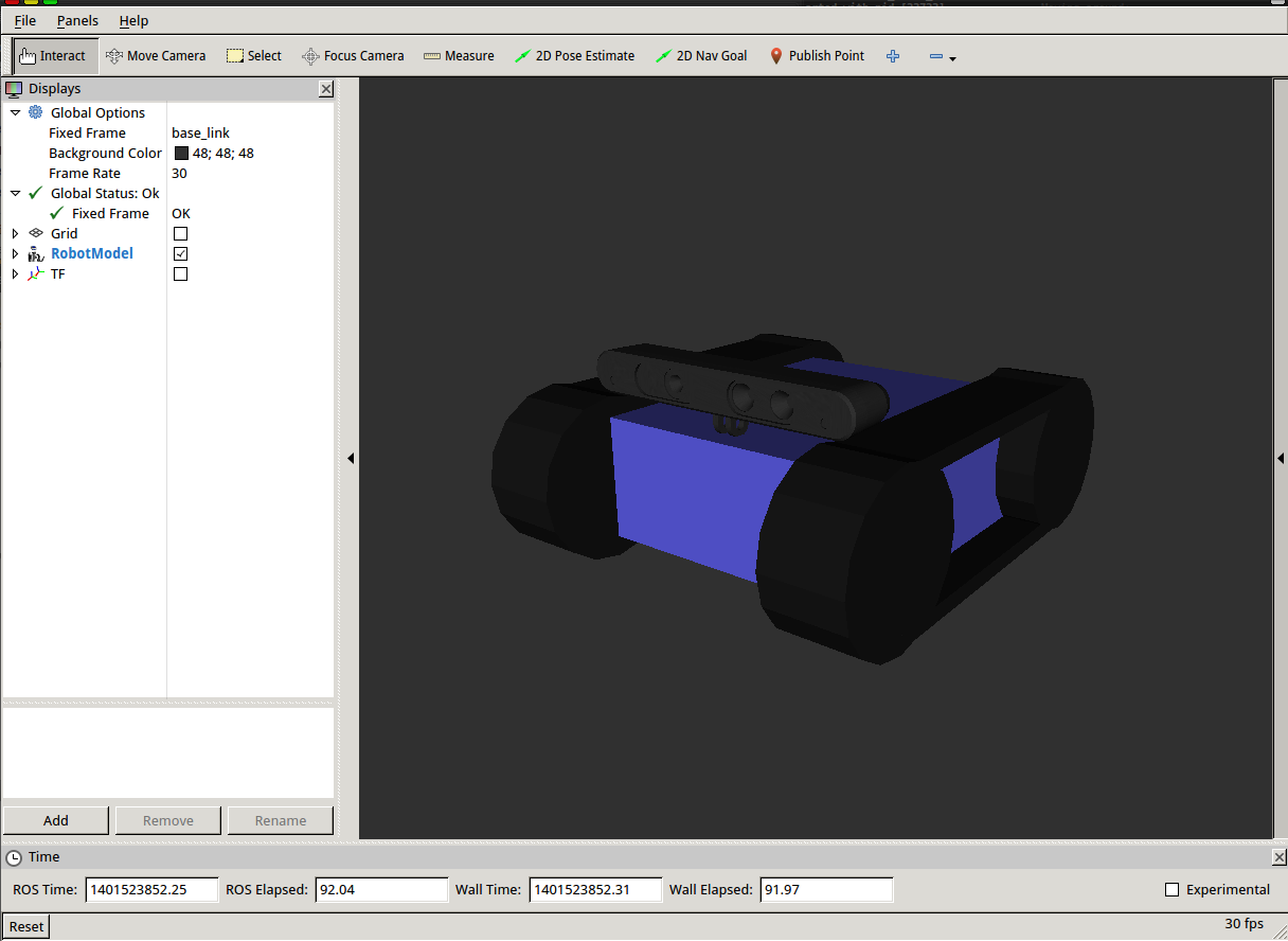
So after starting my customized openni2_launch (the launchers of openni_camera, and both ros drivers) with a custom Openni2 driver dir:

OPENNI2_DRIVERS_PATH=/usr/lib/OpenNI2/Drivers/ roslaunch /home/user/catkin_ws/src/robot_bringup/launch/openni2.launch

(OPENNI2_DRIVERS_PATH fixes all issues with the camera driver nodelet)

its possible to process this down to a /scan topic by:

rosrun depthimage_to_laserscan depthimage_to_laserscan image:=/camera/depth/image_raw

or directly in a launch file using the handy nodelet manager:

  <group>
    <node pkg="nodelet" type="nodelet" name="depthimage_to_laserscan" args="load depthimage_to_laserscan/DepthImageToLaserScanNodelet $(arg camera)/$(arg camera)_nodelet_manager">
      <param name="scan_height" value="10"/>
      <param name="output_frame_id" value="/$(arg camera)_depth_frame"/>
      <param name="range_min" value="0.45"/>
      <remap from="image" to="$(arg camera)/$(arg depth)/image_raw"/>
      <remap from="scan" to="$(arg scan_topic)"/>

      <remap from="$(arg camera)/image" to="$(arg camera)/$(arg depth)/image_raw"/>
      <remap from="$(arg camera)/scan" to="$(arg scan_topic)"/>
    </node>
  </group>

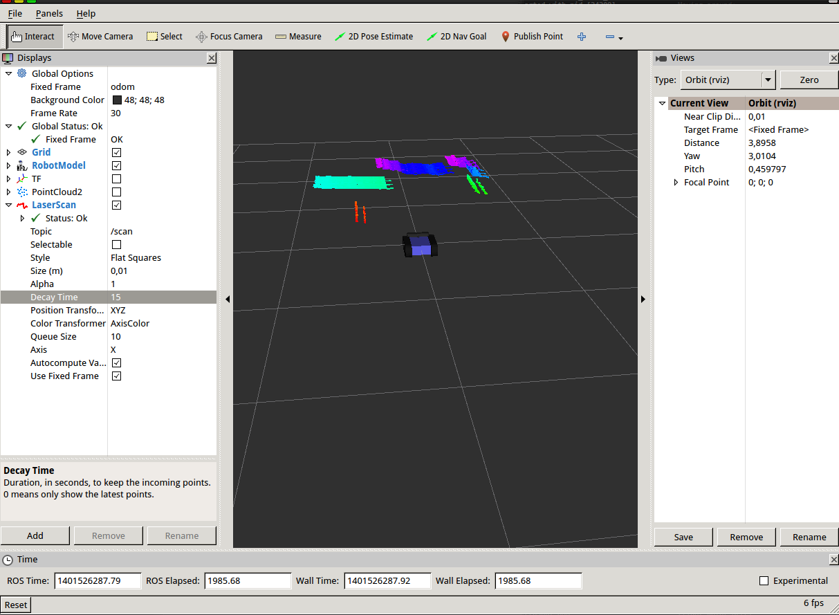
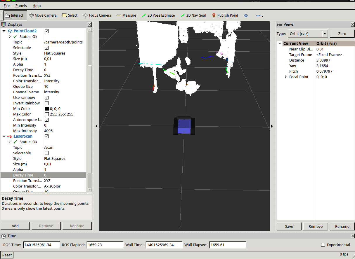
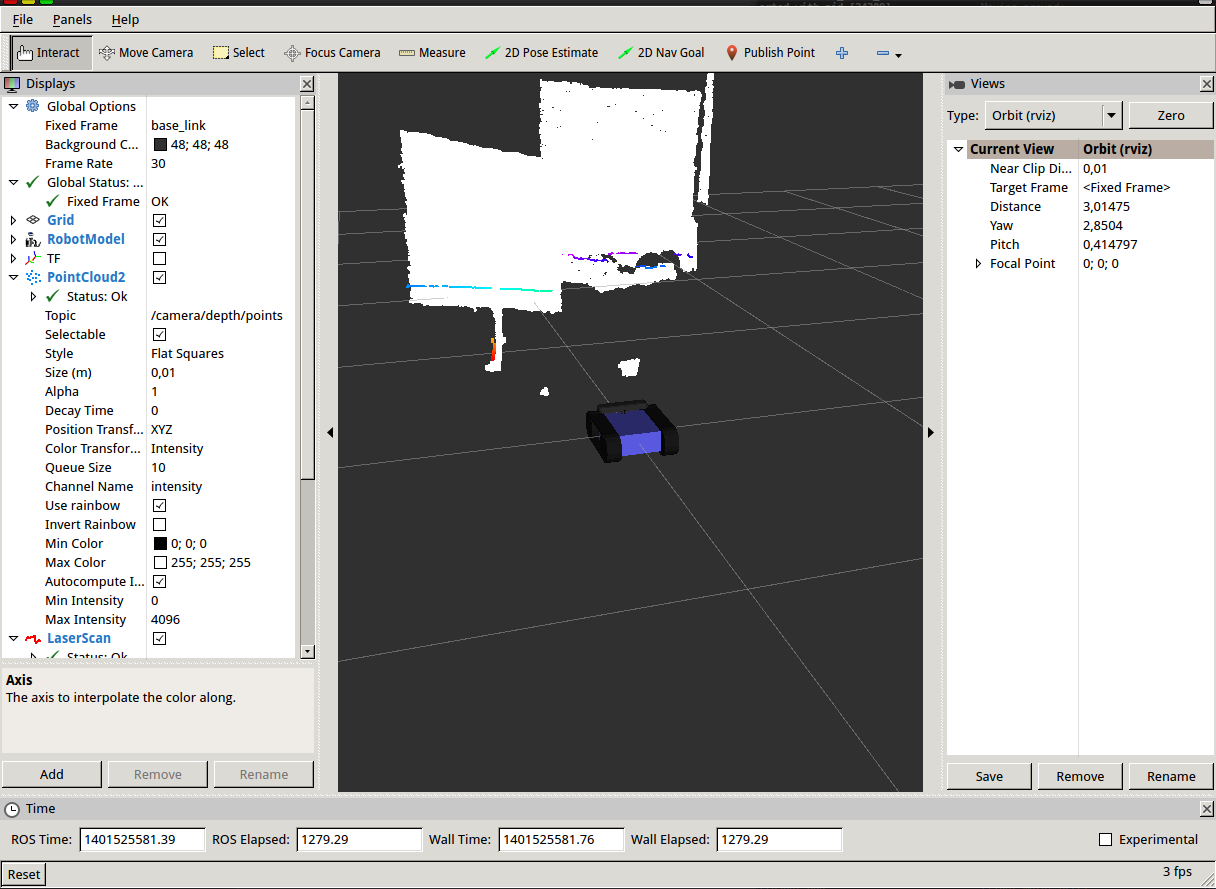
After that it is possible to visualize the new topic using rviz getting something like that:

of course the robot is still able to laserscan with the xtion (now in rainbow indicating z of the camera)