Monthly Archives: June 2014

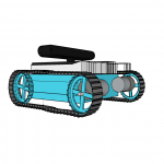
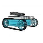
Virtual rearrangement of aMoSeRo One

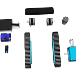
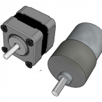
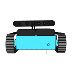
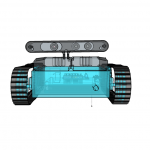
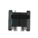
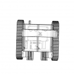
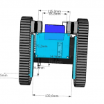
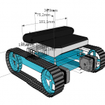
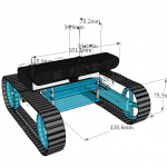
It’s still not easy finding the right combination and arrangement of all robot parts. Like mentioned in the previous post, SketchUp is a nice tool for easy 3D visualization using real physical dimensions. So I spend some time again:

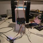
So tomorrow I am trying to by the planned box and the new motors, hopefully posting real world photos soon.

Sketch him up!

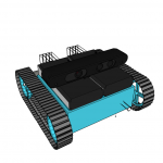
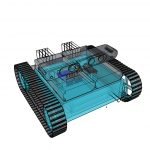
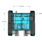
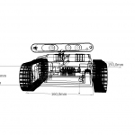
Today I am trying to setup all parts of the coming robot. Because assembling and disassembling would take hours until finding the right configuration and saving steps in between it would be impossible – I thought of a better way. Using my shopworn SketchUp skills and way more time than I expected – finally there is a non perfect but practicable model with the most important parts that are going to be installed. All of them already have the correct physical dimensions which also means that it would be possible to deploy the robot in rviz later, or at least parts of it.

Here are some early stage impressions:

CubiBot1

concept phase: iso view

The wireframe boxes are space required by usb plugs or power jacks. These need to be accessible and can’t be blocked by anything else.

This robot is not ready yet, everything needs to be rearranged and boxed soon. Some parts are still missing, and no cables are shown, so everything will be more packed than it looks like.

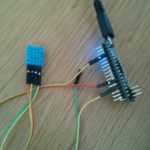
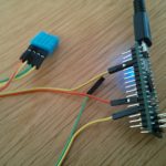
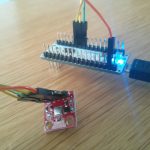
Arduino Micro and temperature+humidity sensor DHT11

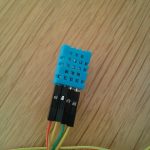
Today is sensor day, so I’ve managed to get the [amazon &title=DHT11&text=DHT11] working:

Wire it like that:
([amazon &title=DHT11&text=DHT11] -> Arduino Micro )

  • Pin 1 (orange cable) to 5V
  • Pin 2 (yellow cable) to GND
  • Pin 3 – not needed
  • Pin 4 (yellow again -.-) to A0

Use the following code I’ve found here:

#include <dht.h>

#define dht_dpin A0 //no ; here. Set equal to channel sensor is on

dht DHT;

void setup(){
  Serial.begin(9600);
  delay(300);//Let system settle
  Serial.println("Humidity and temperaturenn");
  delay(700);//Wait rest of 1000ms recommended delay before
  //accessing sensor
}//end "setup()"

void loop(){
  //This is the "heart" of the program.
  DHT.read11(dht_dpin);

    Serial.print("Current humidity = ");
    Serial.print(DHT.humidity);
    Serial.print("%  ");
    Serial.print("temperature = ");
    Serial.print(DHT.temperature); 
    Serial.println("C  ");
  delay(800);//Don't try to access too frequently... in theory
  //should be once per two seconds, fastest,
  //but seems to work after 0.8 second.
}// end loop()

Getting you a result like that:

It doesn’t seem to be very accurate, but that’s expectable rated by its low price (<2€)


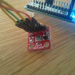
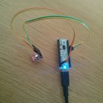
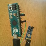
Arduino Micro and barometric pressure sensor BMP180

I’ve experimented with the [amazon &title=BMP180&text=BMP180].  Since its a 3,3V breakout board which is I²C capable I had concerns since the Micro usually uses 5V on its Pins. But without a reason: the I²C on the[amazon &title=BMP180&text=BMP180] needs to get a voltage of 5V and the arduino micro also provides 3.3.
So wiring all together:

Breakout Board -> [amazon &title=Arduino Micro&text=Arduino Micro]
DA -> SDA (Digital 2)
CL -> SCL (Digital 3)
+ -> 3.3 (do NOT plug this to 5V!)
-> GND

Sparkfun offers very good tutorials and source code. The library you’ll need to run this board can be found here

Getting this into your Arduino IDE leads to:

Since its an I²C device it should be stackable with any other I²C device in case they do not have the same BUS-address.


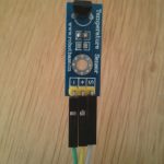
Arduino Micro and temperature sensor LM35

Using the LM35 with the Micro is quite easy.

Just connect:
(LM35 -> [amazon &title=Arduino Micro&text=Arduino Micro] )

  • 5V to positiv
  • GND to
  • S to A4

And run the following code (should run on every arduino):

float temp;
int tempPin = 4;

void setup()
{
  Serial.begin(9600);
}

void loop()
{
  temp = analogRead(tempPin);
  temp = temp * 0.48828125;
  Serial.print("TEMPRATURE = ");
  Serial.print(temp);
  Serial.print("*C");
  Serial.println();
  delay(1000);
}

Getting this result:

Please note its you might need to adjust the 0.48828125 to a value thats verified with another temperature sensor (or just a normal celsius thermometer) .

The next step for me is to write a little ROS publisher for this sensor.


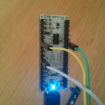
Arduino Micro and Adafruit Motor Shield V2

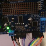
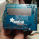
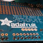
The Adafruit Motor Shield is a very well documented piece of electronics. Its capable of controlling 2 stepper motors or 4 dc motors with a additional possibility of moving 2 servo motors at once(!). So its perfect for small robot projects!
It has four phases of 1,4 Amps maximum current each with an even higher peak current – in case you cool it for instance by a fan it should even take more regular current like the chips datasheets promise. The voltage of the motors should be between 5 and 12 Volts (can be increased to 13 like most car batteries do have at least as long as I’ve connected it to mine for about 30 minutes).

The coolest thing about it is the I²C protocol (and the connected build in PWM-Chip) it speaks. Because of that its stackable with for instance other motor shields and can drive up to 96 Motors with a single i2c signal giver.
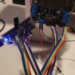
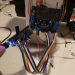
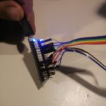
In most cases the signals come from the arduino family, more precisely the Duemilanove, Diecimila, Uno (all revisions), Leonardo and Mega/ADK R3 and higher. As you might recognized, there is no arduino micro in the list, but as it is just a smaller version of the Leonardo it should be possible to work too – right? The answer is: yes it does – at least if you solder right and find the connections that need to be made since the SDA and SCL Pins are digital 2 and 3 on the Micro and A4 and A5 on the shield. Adding 5V, 3V and ground is enough to get it running. (But keep an eye to short circuits and separate powering circuits for the micro)

The i²c protocol (I-squared-C) is supported by the [amazon &title=Raspberry Pi&text=Raspberry Pi] and the [amazon &title=CubieTruck&text=CubieTruck] which means hypothetical it should be possible to run the motor shield with that devices too, but I would not recommend to do so, as there is nearly no code library at the time of this post beeing written.

The motor shield comes with an arduino library where everything gets explained very well. Just one thing they forget to mention is the needed:

#define USE_USBCON

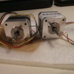
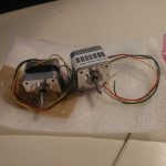
the motors
I’ve got to admit that the motors had been a bad joice so far – they are way to weak. I nearly drove me nuts to get them working, because I couldn’t believe how weak they are 🙂
So I’ve learned a lot about stepper motors datasheets and all of its very confusing unit handling the hard way. And I’ve done the mistake a lot of stepper motor newbies do: assuming the voltage needs to be the same as the batteries voltage. Avoid that thought in case you are building a robot currently 🙂