Tag Archives: Xtion

ROS Basics – depthimage_to_laserscan with low cost depth sensors Asus Xtion or Microsoft Kinect

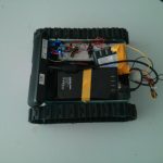
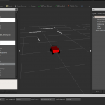
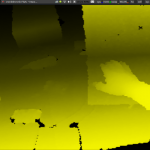
Most of my work depended on the efficient connection between the [amazon &title=Asus Xtion&text=Asus Xtion] and the [amazon &title=CubieTruck&text=CubieTruck] as a low cost laser scanner. As the [amazon &title=Asus Xtion&text=Asus Xtion] usually delivers 3D sensor_msgs/PointCloud  data and most slamming algorithms need 2D sensor_msgs/LaserScan messages to work properly, we need to find a solution to this issue: depthimage_to_laserscan .

If you already managed to use the ros-indigo-openni2-camera and ros-indigo-openni2-launch you can use the following code:

<!-- this code originates from https://github.com/turtlebot/turtlebot/blob/hydro/turtlebot_bringup/launch/3dsensor.launch -->
<launch>
  <!-- "camera" should uniquely identify the device. All topics are pushed down
       into the "camera" namespace, and it is prepended to tf frame ids. -->
  <arg name="camera"      default="camera"/>
  <arg name="publish_tf"  default="true"/>

  <!-- Factory-calibrated depth registration -->
  <arg name="depth_registration"              default="true"/>
  <arg     if="$(arg depth_registration)" name="depth" value="depth_registered" />
  <arg unless="$(arg depth_registration)" name="depth" value="depth" />

  <!-- Processing Modules -->
  <arg name="rgb_processing"                  default="true"/>
  <arg name="ir_processing"                   default="true"/>
  <arg name="depth_processing"                default="true"/>
  <arg name="depth_registered_processing"     default="true"/>
  <arg name="disparity_processing"            default="true"/>
  <arg name="disparity_registered_processing" default="true"/>
  <arg name="scan_processing"                 default="true"/>

  <!-- Worker threads for the nodelet manager -->
  <arg name="num_worker_threads" default="4" />

  <!-- Laserscan topic -->
  <arg name="scan_topic" default="scan"/>

  <include file="$(find openni2_launch)/launch/openni2.launch">
    <arg name="camera"                          value="$(arg camera)"/>
    <arg name="publish_tf"                      value="$(arg publish_tf)"/>
    <arg name="depth_registration"              value="$(arg depth_registration)"/>
    <arg name="num_worker_threads"              value="$(arg num_worker_threads)" />

    <!-- Processing Modules -->
    <arg name="rgb_processing"                  value="$(arg rgb_processing)"/>
    <arg name="ir_processing"                   value="$(arg ir_processing)"/>
    <arg name="depth_processing"                value="$(arg depth_processing)"/>
    <arg name="depth_registered_processing"     value="$(arg depth_registered_processing)"/>
    <arg name="disparity_processing"            value="$(arg disparity_processing)"/>
    <arg name="disparity_registered_processing" value="$(arg disparity_registered_processing)"/>
  </include>

   <!--                        Laserscan 
     This uses lazy subscribing, so will not activate until scan is requested.
   -->
  <group if="$(arg scan_processing)">
    <node pkg="nodelet" type="nodelet" name="depthimage_to_laserscan" args="load depthimage_to_laserscan/DepthImageToLaserScanNodelet $(arg camera)/$(arg camera)_nodelet_manager">
      <!-- Pixel rows to use to generate the laserscan. For each column, the scan will
           return the minimum value for those pixels centered vertically in the image. -->
      <param name="scan_height" value="10"/>
      <param name="output_frame_id" value="/$(arg camera)_depth_frame"/>
      <param name="range_min" value="0.45"/>
      <remap from="image" to="$(arg camera)/$(arg depth)/image_raw"/>
      <remap from="scan" to="$(arg scan_topic)"/>

      <remap from="$(arg camera)/image" to="$(arg camera)/$(arg depth)/image_raw"/>
      <remap from="$(arg camera)/scan" to="$(arg scan_topic)"/>
    </node>
    
  </group>
</launch>

As you might see, the depthimage_to_laserscan gets initialized in a separate nodelet manager.

Nodelets are designed to provide a way to run multiple algorithms on a single machine, in a single process, without incurring copy costs when passing messages intraprocess. (Quote Wiki)

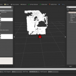
They hugely improve the performance of our 3D point clouds and allow significantly higher publishing rates.

An important property of an robot is the rate of data creation. A low rate influences most
higher algorithms leads to incorrect results. In most cases especially the depth sensors are
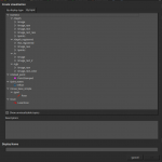
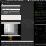
required to publish sufficient material to create detailed maps. The [amazon &title=Asus Xtion&text=Asus Xtion] Pro driver OpenNi2 and the ROS package openni2_camera offers multiple run modes which can be set by dynamic_reconfigure (I suggest using it in combination with rqt). Another essential option influencing performance is the data_skip parameter, which allows the system to skip a certain amount of pictures the hardware produces before loading them into memory and by that remarkably reduces computational load. It can be set to an integer value between zero, which means not to skip any frames at all, and ten, leading to every eleventh frame to be processed.
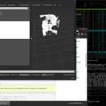
Performance Check

The different combinations of resolutions, maximum frequencies and the data_skip -parameter
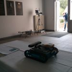
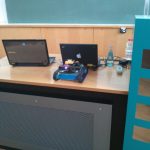
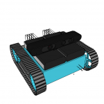
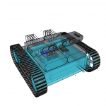
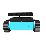
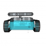
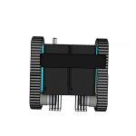
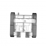
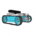
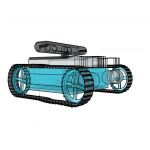
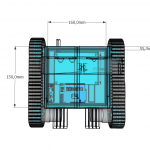
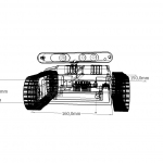
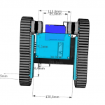
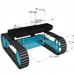
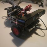
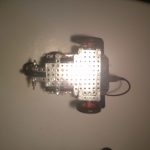
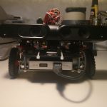
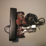
ran on the aMoSeRo (my low cost [amazon &title=CubieTruck&text=CubieTruck] robot) is illustrated in the table below.  As it can be seen, especially the amount of frames that has to be processed per second highly influences the complete system.


In conlusion, the depthimage_to_laserscan package is really useful when working with low cost setups like depth sensors [amazon &title=Asus Xtion&text=Asus Xtion] or the [amazon &title=Kinect&text=Microsoft Kinect]. It furthermore is essential when interfacing SLAM algorithms.

first presentation of aMoSeRo at the BHT Freiberg Germany

Today the BHT which is a mining research forum in Freiberg, Germany took place. As the amosero should run as a support robot in mining somewhen this has been a great chance to firstly show off what we’ve got so far. After 4 weeks from zero to robot:

So we were able to demonstrate the [amazon &title=Asus Xtion&text=Asus Xtion] Features like a live IR Image, some 1fps RGB DepthCloud visualized in RVIZ, driving around including to spot turn.

The plate cookie box we used had some negative effect on the wlan capacity, which we need to address soon by e.g. changing the material or excluding the antenna.

Had been a nice experience showing that little low cost ros robot to public an I am still very exited where the journey leads in the remaining 4 months of my thesis.

Virtual rearrangement of aMoSeRo One

It’s still not easy finding the right combination and arrangement of all robot parts. Like mentioned in the previous post, SketchUp is a nice tool for easy 3D visualization using real physical dimensions. So I spend some time again:

So tomorrow I am trying to by the planned box and the new motors, hopefully posting real world photos soon.

Sketch him up!

Today I am trying to setup all parts of the coming robot. Because assembling and disassembling would take hours until finding the right configuration and saving steps in between it would be impossible – I thought of a better way. Using my shopworn SketchUp skills and way more time than I expected – finally there is a non perfect but practicable model with the most important parts that are going to be installed. All of them already have the correct physical dimensions which also means that it would be possible to deploy the robot in rviz later, or at least parts of it.

Here are some early stage impressions:

CubiBot1

concept phase: iso view

The wireframe boxes are space required by usb plugs or power jacks. These need to be accessible and can’t be blocked by anything else.

This robot is not ready yet, everything needs to be rearranged and boxed soon. Some parts are still missing, and no cables are shown, so everything will be more packed than it looks like.

ROS is about: simulation, simulation and simulation …

ROS needs to know everything about the physics of a robot. It starts with dimension to avoid collusions – both with the outside world and the robot itself (e.g. if it is using two robot arms at once).  Further it is relevant where the sensors are – or in my case where the [amazon &title=Asus Xtion&text=Asus Xtion] is located in relation to the robots base. Another interesting information are the robots joints. Its needed to drive the wheels and to rotate the camera. For all that, a detailed description and representation of the robot in a format that a computer understands is essential.

Today I’ve made a hugh step in the simulation field, so struggeling with the motors in the real world for the last few days doesn’t feel too bad – at least I can generate some nice pictures now:

For me an interesting journey started, with a lot ups and downs – currently I am really excited where we will be in 18 weeks – because 2 weeks of my thesis already passed.

ROS DepthCloud processing distributed

Today I achieved the following setup by dividing my openni2_launch files into two separate launchers beeing executed on two different machines: one for processing (nodelet_managing) running at a powerful server and one for streaming the [amazon &title=Xtion&text=Asus Xtion]-Image data from the [amazon &title=CubieTruck&text=CubieTruck] to the /camera -topic namespace. After that I could visualize, what my laptop wasn’t able to do before: a 3D DepthCloud with RGB-Data coloring in rviz. It has a native resolution of 640*480 and looks like that:

my first ROS 3D DepthCloud

I can’t say how efficient the load is balanced right now – because I am currently still optimizing.


Raspberry Pi Robot with ROS, Xtion, OpenNi2 and rviz providing 3d point cloud data

That’s one small step for a man, one giant leap for a small raspberry powered ROS robot.

Okay – maybe thats a bit too big – but I am in a good mood. I compiled the latest openni2_camera ros driver on the little arm cpu of the [amazon asin=B00LPESRUK&text=[amazon &title=Raspberry Pi&text=Raspberry Pi]]. Before that, I used the driver provided by kalectro (see source), which is an older fork but prepared for raspberry.

As a result of that, I’ve got some new features like the IR-Image stream I visualized with rviz :

Raspberry Pi Robot with ROS

Raspberry Pi Robot with ROS

or the handy little parameter with which it is possible to skip some frames which reduces the load a bit:

set param name="camera/driver/data_skip" value="300"
rosrun openni2_camera openni2_camera_node

Now, running roscore on my laptop – I had some sensor_msg/Images I needed to convert into 3d depth data. After some little issues with faulty XML-launch files, I finally got openni2_launch up and running, which is a handy little launchfile using rgb_launch providing every data format you’ll can get out of the [amazon &title=Xtion&text=Asus Xtion].

roslaunch openni2_camera openni2.launch

Now I’ve had a /camera/depth/points topic, with a pointcloud2 datatype. Which is really nice because rviz can visualize it:

Raspberry Pi Robot with ROS - Xtion

Raspberry Pi Robot with ROS – Xtion

Houston, we’ve had a problem.

Yes, there were times when it was possible to land on the moon by the power of a daily life calculator – but todays robots need more than that 🙂 So my aged Intel Centrino Core 2 Duo ASUS-F3J with 1,7Ghz each core isn’t able to do more than I reached today. It pops to 100% processing and after some time it collapses totally.

So todays lesson learned is:

Robots are distributed systems – by every measure.

So I’ll need more power.. again…

Raspberry Pi Robot #1

I’ve completed a new version today. It is a bit smaller and heavier, but already running ros hydro (I will write a small tutorial soon how to achieve that) with OpenNI2 and the ros-package openni2-camera. With that its possible to stream data to another computer visualizing the depth image of the [amazon &title=Asus Xtion&text=Asus Xtion] in rviz. I had some trouble solving and compiling all drivers, dependencies like ros-packages and libs like openCV (see Howto).

When the camera node is running the Raspberry is faced at with a processing load of 100%. The used network bandwidth is about 200-300 kb/s.

I suppose the raspberry Pi needs to be replaced by something stronger soon.

But for my first week in robotics, it’s something 🙂


Raspberry Pi Robot #0

I am trying to build my own [amazon &title=Raspberry Pi&text=Raspberry Pi] based robot. Someday, it shall be able to drive autonomously based on data from its [amazon &title=Asus Xtion&text=Asus Xtion] (a smaller version of an Xbox Kinect) and with the help of ROS (Robot Operating System). For today, it is only capable of driving straight forward.

PiRosBot #Zero

Parts:

  • [amazon &title=Asus Xtion&text=Asus Xtion] Pro
  • a [amazon &title=Raspberry Pi&text=Raspberry Pi] Model B Rev.2.0
  • WLAN USB stick
  • two Stepper Motors 28BYJ-48 Datasheet PDF 5V controlled by an ULN2003A Chip
  • an easyAcc Powerbank with 10.000mhA with an MicroUSB Cable supplying 2A of power
  • some metal toy constuction set parts including 3 wheels
  • 8 old female to female jumper wires
  • 2 Y female jumper whires (to share positive and ground of the raspberry with the motors)

With this setup, the raspberry i able to run at least 8 hours by the power of my already a little bit aged powerbank. Driving at an unbelievable slow speed of about 30 seconds per meter (full torque mode of steppers).

For documentation (and for fun, because I never did this before), here a small video of the very first test drive:

Youtube Video