Category Archives: ROS

ROS – [rosout-1] process has died, exit code -11

Some days ago I started roscore and got faced with an error message like that:

process[rosout-1]: started with pid [16089]
[rosout-1] process has died [pid 16089, exit code -11, cmd /opt/ros/indigo/lib/rosout/rosout __name:=rosout __log:=/home/rosuser/.ros/log/9b3b3980-0b60-11e4-80f9-0015afdb2ab9/rosout-1.log].
log file: /home/rosuser/.ros/log/9b3b3980-0b60-11e4-80f9-0015afdb2ab9/rosout-1*.log

Okay, so roscore seemed to have crashed and created a log file according to the given path. But the logfile was empty *please imagine dramatic sound effects here*. But what do you do, if a programm (rosout?) crashes without log file and an error message like the above?

You insert your well done system wide backups like snapshots from zfs,btrfs, virtual machines, lvm or anything. If you forgot to do so… *fail sound here* you might need to manually check what changed since the last time it worked.

And so I did. For several days.

I soon figured out, that this error applied to all rosccp related ROS-programms – but left all rospy parts alive, which finally put my on track that there has been an kernel update of my ubuntu 14.04, which I unfortunately installed in a moment of weak decisions.
So reverting that would have been been an option, further my lib-boost version seemed to have changed – since ROS is very sensible to that, this might have been the problem. Therefore I tried everything by manually reverting updates, reinstalling packages, recompile everything from source, searching system logs and soon really considered to reset my system by installing good old 13.04 with ROS hydro…

But wait! Sometimes you strike lucky and time solves all issues. Today I’ve just upgraded my ROS from their repos and tadaaa – everything works again.

But why do I write this into an post? Because its easy to avoid situations like that and I want to share my hard learned lessons with you the easy way:

  1. Get your ROS version straight – Do you really need the latest ROS on the latest kernel?
    The answer for your system is probably no. I am currently running stable ROS Hydro and ‘unstable’ ROS Indigo on Ubuntu 14.04 on latest kernel. It works – but it would have been way easier to stick on Hydro all the way.
  2. avoid apt-get dist-upgrade on critical ROS machines
  3. use backups and / or virtual machines
  4. rospy didn’t cause any problems so far – in case performance isn’t the most important thing, think about using python
  5. avoid to put all your catkin_ws code into one git repository  if its running on multiple architectures (x86,x64, arm6,arm7) – alone the openni2_driver took nearly all my sanity during learning that lesson….

That is enough for today, but after this list, I really think about tracking all hard learned lessons in more public and better organised location – ROS best practices? We’ll see.

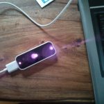


LeapMotion and ROS

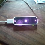
Today I’ve got the chance to get my hands on a Leap Motion. As it uses depth information to track hands on a short range from the device and as there is a ros driver package existing for it, I hoped to get a 3D PointCloud. It costs about 80€ and could have been a cheap replacement for the [amazon &title=Xtion&text=Asus Xtion].

Unfortunately its not possible (yet?) – here is a very nice post why.

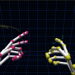
But it is fun anyways to get both hands tracked:

Youtube Video

The ros driver interfaces ros with only one hand – but we could do something like shown below to control the amosero:

Youtube Video

Later it would be a nice way to control a robot arm – but for now we leave that nice little device as there is a lot of other stuff to be done.

aMoSeRo – first robot_pose_ekf and gmapping

This surely doesn’t look amazing from a external look – but this has been a day of hard work and was very important.

The robot_pose_ekf package is working! It is neither the setup I am going to use nor is it very stable – but it proves some points.

First I needed to write my own IMU driver for ros – 9 degrees of freedom (DOF) for 30€ and a bag of problems. This is a lot cheaper (around 100€) than the often used Razor IMU of sparkfun with existing ROS code, and exactly 3DOF better than the WiiMote (with Motion+ and also about 60-70€) I have been experimenting with. There is still a lot of work left for improving the stability, the calibration of the LSM9DS0 and there has been a lot more to find out about magnetic fields and strange units that needed to be converted in other ones than I would have ever expected – but so far the /imu_data topic serves some not totally wrong data – therefore normalisation minimizes  the issues with the 3-5 scales per axis I had to deal with.

Next I needed to increase my bad odometry sources – if not by quality at least with quantity – and added a GPS sensor as /vo topic.  The CubieTruck is a abstruse while handling some easy things like using one of the possible 8 UART connections…  for today I’ve not managed to get it running with UART but a external serial usb controller. Another area that needs heavy improvement…

Finally I had to deal with the REP105 issue that I have been describing in a previous post. The gmapping algorithm needed to get adjusted parameters, coming along with some serious confusion generated by inconsistent syncing over my 4 working devices (rosBrain with roscore and slamming, rosDev – my development machine, the aMoSeRo and the seafile backup server)…

…but after that all parts worked together for the first time, including a simulated aMoSeRo moving on screen while beeing hold in different angles in the real world.

Everything is still far from done – but right on the way – and we’ve already found out how wide the road is 🙂

Willow Garage, the PR2 and REP105

It is the second time I need to adjust my URDF Model for the sake of NOT following the REP (ROS Enhancement Proposal). This time it is about the relationship between base_link and a not REP mentioned base_footprint.

As REP105 says the ‘Relationship between Frames’ should be:

map –> odom –> base_link

but the relation chip for the Willow Garage (or now Clearpath Roboticsrobot PR2 is

map --> odom_combined --> base_footprint  -->   base_link

which is the exact demand of the robot_pose_ekf package.

So Willow Garage, Y U NO Stick to your own REP105 ?

(See more on Know Your Meme)

I suppose because of backwards compatibility, some code might get broken, but what about using some parameters, maybe with a (even hard coded) default fallback?

So for the aMoSeRo there is a decision to be made. Using base_link or base_footprint? Or both? Which frame is the one near to earth?

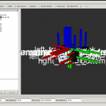
If decided to take both as a matter of compatibility to other packages and reordered my TF tree:


framesWithParentFootprint


Still questionable if the base_footprint should have wheels and tracks attached, but that is more a question of taste because they have no special task.

Screenshot - 04.07.2014_4


Now the robot has a light grey base_footprint, and a blue base_link.

aMoSeRo – first Simultaneous Planning Localization and Mapping (SPLAM)

Far from done, but right on the way – the aMoSeRo did his first 2D planning today.  There are still a lot of adjustments needed for the mapping to work properly, but it’s already impressive to see ROS working.

first SPLAM - first navigation through a map

first SPLAM – first navigation through a map

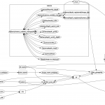
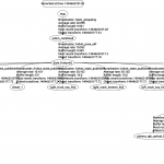
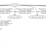
The node graph still grows and will need some changes when used with multiple robots, but organising goes on 🙂

first SPLAM - it is getting even worse, more topics, more nodes

aMoSeRo – very first mapping view available

After days with latex and struggling with all sensor data a mobile robot needs, today is the first day of ROS showing me a small map view. It’s anything but stable and I can’t claim understanding everything – but because I’ve hadn’t something to report for some time now here a small demonstration:

First Mapping Experience

Screenshot fromMAP

ScreenshotTopics Topics Overview – amosero a distributed system still far from optimal

Because my IMU doesn’t do its work as it should, I’ve used a WiiMote Motion + and run it by a common ros driver and bluetooth.

Yeeeha 🙂

ROS Hydro/Indigo and sparkfun IMU LSM9DS0 9DOF

I’ve connected the LSM9DS0 9 degrees of Freedom Breakout Board made by sparkfun with an arduino micro like I’ve described in a previous post, wrote a little rosserial sensor_msgs::Imu publisher and visualized everything using the rqt plugin manager for further experimenting.

Here a screenshot while moving the setup:

ScreenshotIMURos

a screenshot while not touching:

ScreenshotIMURos2

As you see all data is still moving a lot. So the next step beside finding out what the units really mean, will be stabilizing by using a kalman filter like its provided in the robot_pose_ekf package.

By the way: the arduino is currently using around 25000 of its 28 672 bytes memory just providing the IMU data to ros. So the motorshield will require another micro or we switch it to something else like an wiimote.

ROS Transformation and Odometry based on URDF Convention REP103

In order to get ROS working correctly, you need a lot things to be set up according to ROS defined conventions: for instance the ‘Standard Units of Measure and Coordinate Conventions’ (REP103), which clearly explains which units geometry_msgs.Twist should have or in what movement direction your robot need to be inside its URDF file.

For me this meant to redo my xacro (URDF-Macro) defined robot driving direction and its according tf-links. Since I’ve already gained some experience in creating robot models I tried to improve it a bit too:

I will explain the robots hardware setup in another post as soon as its possible to run it by keyboard teleop while publishing its accurate odometry. Odometry Messages aren’t simply ROS transformations like moving parts of the robot. Because the robot belongs to the physical world where for example friction exists and further wheel jamming could happen, all the calculated position data need to by verified. Qualified for this task is sensor data like Ultrasonic Sensor Ranges, motor potentiometer or stepper motor positions or Openni2 data provided by the [amazon &title=Xtion&text=Asus Xtion]. After publishing this Odometry messages to the /odom topic, the ros navigation packages can generate geometry/Twist messages to correct the position to mach the simulation again in case there has been some deviation.

More on this topic soon.

ROS Hydro / Indigo PointCloud to Laserscan for 2D Navigation

UPDATE: see my step by step guide for depthimage_to_laserscan here.

PointClouds need a lot of processing and network traffic load. For 2D navigation LaserScans are a good option to decrease this loads, in my case below to 30% of the original.

So after starting my customized openni2_launch (the launchers of openni_camera, and both ros drivers) with a custom Openni2 driver dir:

OPENNI2_DRIVERS_PATH=/usr/lib/OpenNI2/Drivers/ roslaunch /home/user/catkin_ws/src/robot_bringup/launch/openni2.launch

(OPENNI2_DRIVERS_PATH fixes all issues with the camera driver nodelet)

its possible to process this down to a /scan topic by:

rosrun depthimage_to_laserscan depthimage_to_laserscan image:=/camera/depth/image_raw

or directly in a launch file using the handy nodelet manager:

  <group>
    <node pkg="nodelet" type="nodelet" name="depthimage_to_laserscan" args="load depthimage_to_laserscan/DepthImageToLaserScanNodelet $(arg camera)/$(arg camera)_nodelet_manager">
      <param name="scan_height" value="10"/>
      <param name="output_frame_id" value="/$(arg camera)_depth_frame"/>
      <param name="range_min" value="0.45"/>
      <remap from="image" to="$(arg camera)/$(arg depth)/image_raw"/>
      <remap from="scan" to="$(arg scan_topic)"/>

      <remap from="$(arg camera)/image" to="$(arg camera)/$(arg depth)/image_raw"/>
      <remap from="$(arg camera)/scan" to="$(arg scan_topic)"/>
    </node>
  </group>

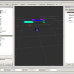
After that it is possible to visualize the new topic using rviz getting something like that:

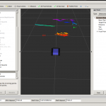
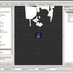
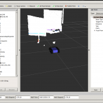
of course the robot is still able to laserscan with the xtion (now in rainbow indicating z of the camera)


ROS is about: simulation, simulation and simulation …

ROS needs to know everything about the physics of a robot. It starts with dimension to avoid collusions – both with the outside world and the robot itself (e.g. if it is using two robot arms at once).  Further it is relevant where the sensors are – or in my case where the [amazon &title=Asus Xtion&text=Asus Xtion] is located in relation to the robots base. Another interesting information are the robots joints. Its needed to drive the wheels and to rotate the camera. For all that, a detailed description and representation of the robot in a format that a computer understands is essential.

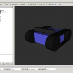
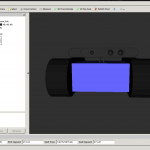
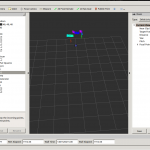
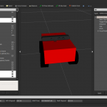
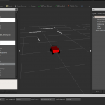
Today I’ve made a hugh step in the simulation field, so struggeling with the motors in the real world for the last few days doesn’t feel too bad – at least I can generate some nice pictures now:

For me an interesting journey started, with a lot ups and downs – currently I am really excited where we will be in 18 weeks – because 2 weeks of my thesis already passed.