Today the BHT which is a mining research forum in Freiberg, Germany took place. As the amosero should run as a support robot in mining somewhen this has been a great chance to firstly show off what we’ve got so far. After 4 weeks from zero to robot:
-
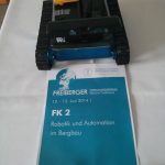
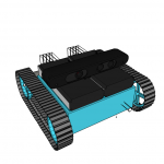
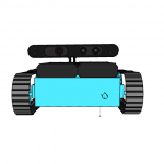
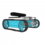
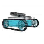
- BHT – front view
-
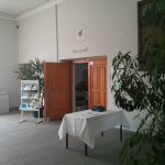
- BHT – 10:05 am waiting in front of the lecture hall
-
- BHT – other drones are near by
-
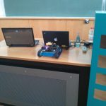
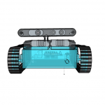
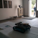
- BHT – moments before the presentation, the IR Camera is clearly running
-
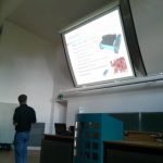
- BHT – during lecture hold by my academic advisor
-
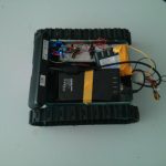
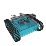
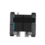
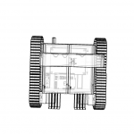
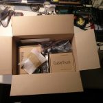
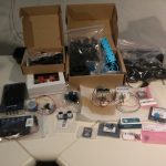
- BHT – view inside the box – not yet well organized, but working
So we were able to demonstrate the [amazon &title=Asus Xtion&text=Asus Xtion] Features like a live IR Image, some 1fps RGB DepthCloud visualized in RVIZ, driving around including to spot turn.
The plate cookie box we used had some negative effect on the wlan capacity, which we need to address soon by e.g. changing the material or excluding the antenna.
Had been a nice experience showing that little low cost ros robot to public an I am still very exited where the journey leads in the remaining 4 months of my thesis.