Monthly Archives: May 2014

Howto run a 12V bipolar stepper motor with arduino micro and L298N at 150rpm

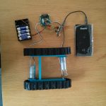
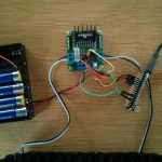
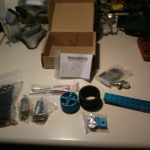
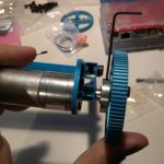
Today I experimented with a 12V bipolar stepper motor and the 5V arduino micro.

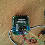
To get things working I’ve put the 9V from my six 1.5V Batteries into an UBEC which accelerates them to 12V at a loss of below 10% (at 350mAh) connected them to the VCC of the L298N and wired the 4 signal cables of the motors to it. Because thats a lot of numbers to keep track of – I’ve made a small video of the setup:

Youtube Video

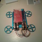
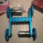
Doing the math according to a wheel with 5,8cm heigth and 150rpm I’ve reached, my robot will be able to run about 1,6 km/h – this might be increased with a better motor driver like they used on the arduino motor shield. I’ve read they reached about 250 rpm on the same motor which would be 2,73km/h.

The code of the arduino is pretty simple:

#include <Stepper.h>

const int stepsPerRevolution = 200;  // change this to fit the number of steps per revolution
// for your motor


// init the stepper lib on pins 8 through 11:
Stepper myStepper(stepsPerRevolution, 8,9,10,11);            

void setup() {
  // nothing to do inside the setup
}

void loop() {
    myStepper.setSpeed(150);
    myStepper.step(stepsPerRevolution/100); 
}


ROS DepthCloud processing distributed

Today I achieved the following setup by dividing my openni2_launch files into two separate launchers beeing executed on two different machines: one for processing (nodelet_managing) running at a powerful server and one for streaming the [amazon &title=Xtion&text=Asus Xtion]-Image data from the [amazon &title=CubieTruck&text=CubieTruck] to the /camera -topic namespace. After that I could visualize, what my laptop wasn’t able to do before: a 3D DepthCloud with RGB-Data coloring in rviz. It has a native resolution of 640*480 and looks like that:

my first ROS 3D DepthCloud

I can’t say how efficient the load is balanced right now – because I am currently still optimizing.


Howto run two 6V DC motors with arduino micro

So before trying to get the planned stepper motors running, I quickly put a dc motors setup together:

I’ve got two dc motors coming with my make block robot starter kit. And for research I also ordered a small l298n motor controller shield which is able to control motors up to 24Vs and 2A each by  4 small input wires at  for example 3,3V and 2 additional +5V motor enablers.

There is a nice little page which explains all states of the L298N according to the arduino micro here. For a [amazon &title=Raspberry Pi&text=Raspberry Pi] I found a nice Youtube video explaining everything here.

For me in the end both motors rotated quite nicely, like this video shows:

Youtube Video

For the micro I wrote this peace of code:

const int IN1 = 10;
const int IN2 = 11;
const int IN3 = 8;
const int IN4 = 9;

void setup()
{
  pinMode(IN1, OUTPUT);
  pinMode(IN2, OUTPUT);
  pinMode(IN3, OUTPUT);
  pinMode(IN4, OUTPUT);
}
 
void loop()
{
  digitalWrite(IN1, HIGH);
  digitalWrite(IN2, LOW);  
  digitalWrite(IN3, HIGH);
  digitalWrite(IN4, LOW);
  
  //hold speed fro 5 seconds
  for(byte j = 5; j > 0; j--) 
  {
    delay(1000);
  }
  
  //stop for two seconds.
  digitalWrite(IN1, LOW);
  digitalWrite(IN2, LOW);  
  digitalWrite(IN3, LOW);
  digitalWrite(IN4, LOW);
  delay(2000);
  
  //switching direction
  digitalWrite(IN1, LOW); 
  digitalWrite(IN2, HIGH);  
  digitalWrite(IN3, LOW); 
  digitalWrite(IN4, HIGH);
 

 //hold speed for 5 seconds
 for(byte u = 5; u > 0; u--)
  {
    delay(1000);
  }
}


Makeblock Robot Kit unboxing

At www.makeblock.cc its possible to buy aluminium robot parts and as I did (or better said, like the university did, because they paid for) complete assembly kits. This one is the starter kit blue and costs about 70€ at the local distributor. So I made some photos for documentation and fun:

Sadly the screws make scratches to the blue surface. So in case you plan multiple designs, there is no way to avoid them but to use some washers.

Howto use CubieTruck and tightVNCserver

VNC is a nice tool for remote desktop administration. But like a lot of things, it doesn’t work out of the box on the [amazon &title=CubieTruck&text=CubieTruck].

After installing the tightvncserver with

sudo apt-get install tightvncserver

I started and configured the server with

tightvncserver

and tried to login to [amazon &title=CubieTruck&text=CubieTruck]IP:5091 I got a grey screen and nothing more happend. So I suppose thats a blank X instead the Lxde I expected.

So tighvnc server has a small script thats executed after you login with vnc to a server, it is located at ~/.vnc/xstartup and contains by default something like that:

#!/bin/sh

xrdb $HOME/.Xresources
xsetroot -solid grey
#x-terminal-emulator -geometry 80x24+10+10 -ls -title "$VNCDESKTOP Desktop" &
#x-window-manager &
# Fix to make GNOME work
export XKL_XMODMAP_DISABLE=1
/etc/X11/Xsession

So the VNC really starts a Xsession.. simply comment the last line out (use a #) and add this:

/usr/bin/lxsession -s Lubuntu -e LXDE

Now it should be possible to use a vnc viewer of your joice – like remmina and connect to your [amazon &title=CubieTruck&text=CubieTruck] using the 5901 port:

Screenshot - 13.05.2014 - 20:09:21


Howto get a CubieTruck WLAN working

Note: Please see the new version of this post

For some reason the WLAN of the [amazon &title=CubieTruck&text=CubieTruck] didn’t work out of the box. So to save you the day I spent to get it working I wrote this little step by step tutorial:

1. load the wlan driver by typing

modprobe bcmdhd

in case you don’t want to do that everytime the [amazon &title=CubieTruck&text=CubieTruck] needs wifi consider adding a new line with ‘bcmdhd’ (no quotes) to /etc/modules

2. install linux-firmware

sudo apt-get install linux-firmware -y

and reboot

sudo reboot

3. bring the wlan0 device up and scan if your wlan is available

sudo -i #get root 
ifconfig wlan0 up
iwlist wlan0 scan

4. add this wlan to your connection configuration file (replace yourSSID and yourPasswd accordingly)

sudo -i #get or stay root
wpa_passphrase yourSSID yourPasswd >> /etc/wpa_supplicant.conf

5. add following lines to /etc/network/interfaces

auto wlan0
iface wlan0 inet dhcp
wpa-conf /etc/wpa_supplicant.conf

6. add DNS Information to /etc/resolv.conf (attention, we’ll use google in that example)

nameserver 8.8.8.8

7. restart networking to get changes to action

sudo service networking restart

If everything went well, your wlan0 device should have an IP when checking it with

ifconfig wlan0 

Arduino Micro and ultrasonic sensor HC-SR04

This is my very first arduino application. But its simple and amazing.

You will need 4 female to female jumper wires and [amazon &title=HC-SR04&text=HC-SR04] ultrasonic sensor, a microusb cable and in the end you’ll be able to measure distances with this little device.

Just wire it like shown below:

IMG_20140513_173350

I used pins 7 (orange echo) and 8 (yellow trigger) for data pins, 5V(red) and ground(black).

I have taken some code from this page. The result you can see in the screenshot below, its a amount of cm written in the serial console:

Screenshot - 13.05.2014 - 17:37:28

/*
 [amazon &title=HC-SR04&text=HC-SR04] Ping distance sensor:
 VCC to arduino 5v 
 GND to arduino GND
 Echo to Arduino pin 7 
 Trig to Arduino pin 8
 
 This sketch originates from Virtualmix: http://goo.gl/kJ8Gl
 Has been modified by Winkle ink here: http://winkleink.blogspot.com.au/2012/05/arduino-hc-sr04-ultrasonic-distance.html
 And modified further by ScottC here: http://arduinobasics.blogspot.com.au/2012/11/arduinobasics-hc-sr04-ultrasonic-sensor.html
 on 10 Nov 2012.
 */


#define echoPin 7 // Echo Pin
#define trigPin 8 // Trigger Pin
#define LEDPin 13 // Onboard LED

int maximumRange = 200; // Maximum range needed
int minimumRange = 0; // Minimum range needed
long duration, distance; // Duration used to calculate distance

void setup() {
 Serial.begin (9600);
 pinMode(trigPin, OUTPUT);
 pinMode(echoPin, INPUT);
 pinMode(LEDPin, OUTPUT); // Use LED indicator (if required)
}

void loop() {
/* The following trigPin/echoPin cycle is used to determine the
 distance of the nearest object by bouncing soundwaves off of it. */ 
 digitalWrite(trigPin, LOW); 
 delayMicroseconds(2); 

 digitalWrite(trigPin, HIGH);
 delayMicroseconds(10); 
 
 digitalWrite(trigPin, LOW);
 duration = pulseIn(echoPin, HIGH);
 
 //Calculate the distance (in cm) based on the speed of sound.
 distance = duration/58.2;
 
 if (distance >= maximumRange || distance <= minimumRange){
 /* Send a negative number to computer and Turn LED ON 
 to indicate "out of range" */
 Serial.println("-1");
 digitalWrite(LEDPin, HIGH); 
 }
 else {
 /* Send the distance to the computer using Serial protocol, and
 turn LED OFF to indicate successful reading. */
 Serial.println(distance);
 digitalWrite(LEDPin, LOW); 
 }
 
 //Delay 50ms before next reading.
 delay(50);
}


Rasberry Pi Robot with ROS, Xtion and working base_controller teleop

Before I dismantle my little [amazon &title=Raspberry Pi&text=Raspberry Pi] Robot #1 , I wanted to have a little video of its base_controller working together with the turtlebot teleop. It uses the geometry/Twist messages to transmit moving information like a lot of ROS Robots do.

Youtube Video

As you see there is a little acceleration control implemented which makes the robot start smoothly and stop after gently after no key is pressed anymore. In case of emergency its possible to hit e.g. the space bar for a instant full stop.

This robot isn’t very fast – but the next one will be. So this was a successful ROS-learning robot which I can recommend to everyone who wants to know how ROS Robots work.
Its a bit hard to get all of the source compiled on the small arm cpu, and there are nearly no precompiled packages – but it takes away all the fear from compiling errors in the future 🙂


CubieTruck (CubieBoard 3) unboxing

The CubieTruck (or so called Cubieboard 3) is the third board of CubieTeam. It is a new PCB-Version with a Allwinner A20 Chip, which has also been used in the CubieBoard 2. But now there is more RAM (2GB) and onBoard VGA-graphics Controller, onBoard Wifi (!) and BLuetooth. There are some more features mentioned below, but for my project the main advantages are: more processing power (2 stronger cores), lower power consumption (500mAh at 5V), lots of GPIOs (2mm!) and flash memory.

So I unboxed one today:

It came with an android os flashed. So after some reading and kinda confusing tutorials I managed to get the correct version 13.04 of lubuntu server running on a sd card, installed ROS on it and was faced with some kind of paradies of ros hydro armhf packages!
Something I was really missing at the [amazon &title=Raspberry Pi&text=Raspberry Pi].

So after the first day of CubieBoard I am really looking forward to get this little fellow beeing the heart of my ROS Robot.

Features:

  • Allwinner Tech A20 SOC
  • SATA supported
  • 54 extended pins
  • Built-in HDMI/ VGA display interface
  • Built-in WIFI+BT module
  • 2GB DDR3 RAM
  • Built-in IR receiver
  • SPDIF audio interface

Specifications:

  • Allwinner Tech SOC A20 ARM® Cortex™-A7 Dual-Core ARM® Mali400 MP2 Complies with OpenGL ES 2.0/1.1
  • 2GB DDR3@480MHz
  • HDMI&VGA 1080P display output on-board
  • 10M/100M/1G Ethernet
  • WIFI + BT wireless connection with antenna on-board
  • SATA 2.0 interface support 2.5’ HDD (for 3.5’ HDD, only need another 12V power input)
  • Storage solution NAND + MicroSD
  • 2 x USB HOST, 1 x OTG, 1 x SPDIF, 1 x IR, 4 x LEDs, 1 x Headphone, 3 x Keys
  • Power DC5V@2.5A with HDD support Li-battery & RTC
  • 54 extended pins including I2S, I2C, SPI, CVBS, LRADC x2,UART, PS2, PWM x2, TS/CSI, IRDA, LINEIN&FMIN&MICIN, TVIN x4 with 2.0 pitch connectors
  • PCB size 11cm *8cm*1.4mm

brace yourself more posts are coming

Today the new parts arrived, which is why there will be a lot of new posts soon.

There is a [amazon &title=CubieTruck&text=CubieTruck] in it, better stepper motors, a lot of sensors, tracks and wheels – so a lot of work in a box 🙂