
In order to get ROS working correctly, you need a lot things to be set up according to ROS defined conventions: for instance the ‘Standard Units of Measure and Coordinate Conventions’ (REP103), which clearly explains which units geometry_msgs.Twist should have or in what movement direction your robot need to be inside its URDF file.
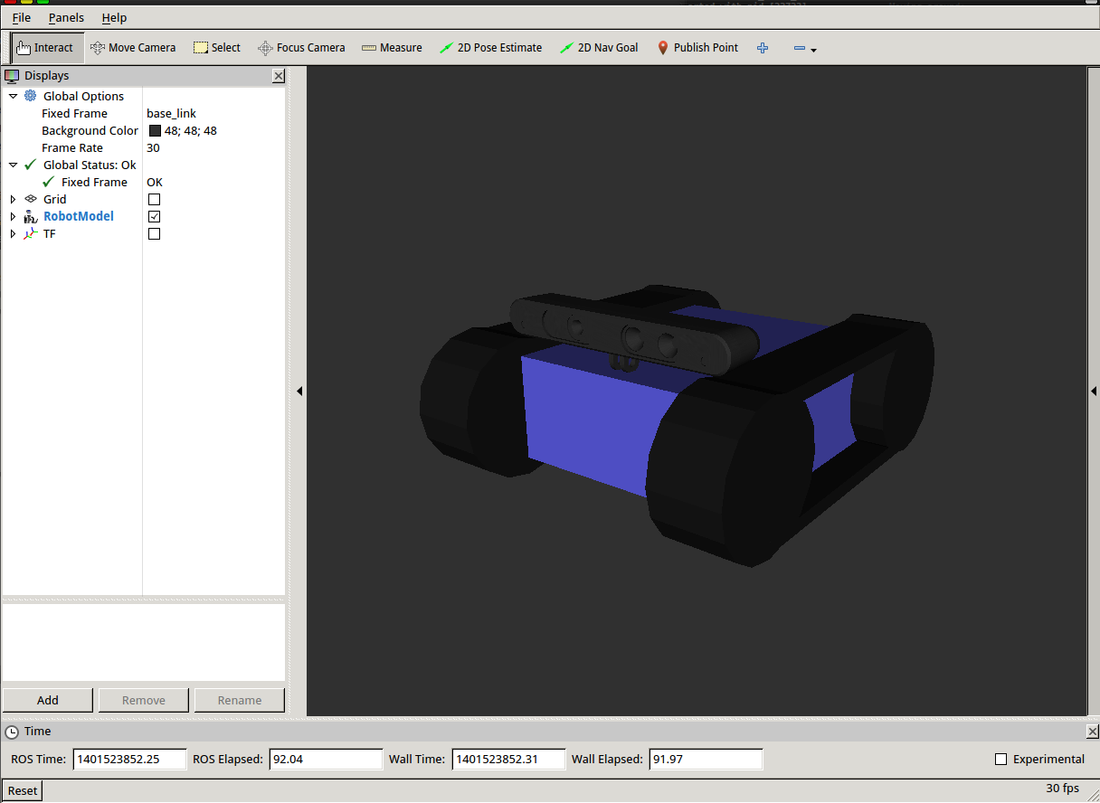
For me this meant to redo my xacro (URDF-Macro) defined robot driving direction and its according tf-links. Since I’ve already gained some experience in creating robot models I tried to improve it a bit too:
-
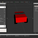
- Now the robot has modeled tracks and pretty much his real physical dimensions
-
- The xtion is a sketch-up .dae file I’ve borrowed from the turtlebot

-
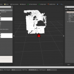
- now the robot aims towards positiv x-axis

-
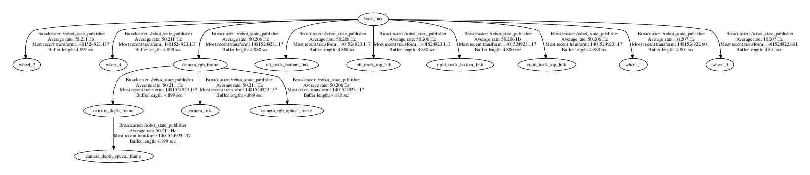
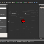
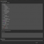
- the frame tree slightly grew
-
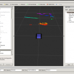
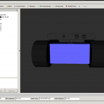
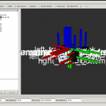
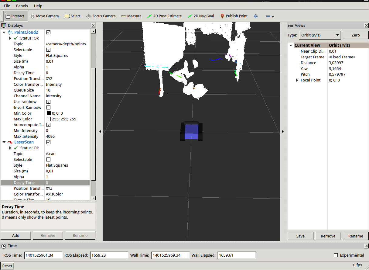
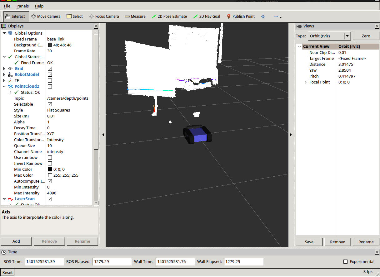
- of course the robot is still able to laserscan with the xtion (now in rainbow indicating z of the camera)

-
- even while published fake transform
-
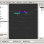
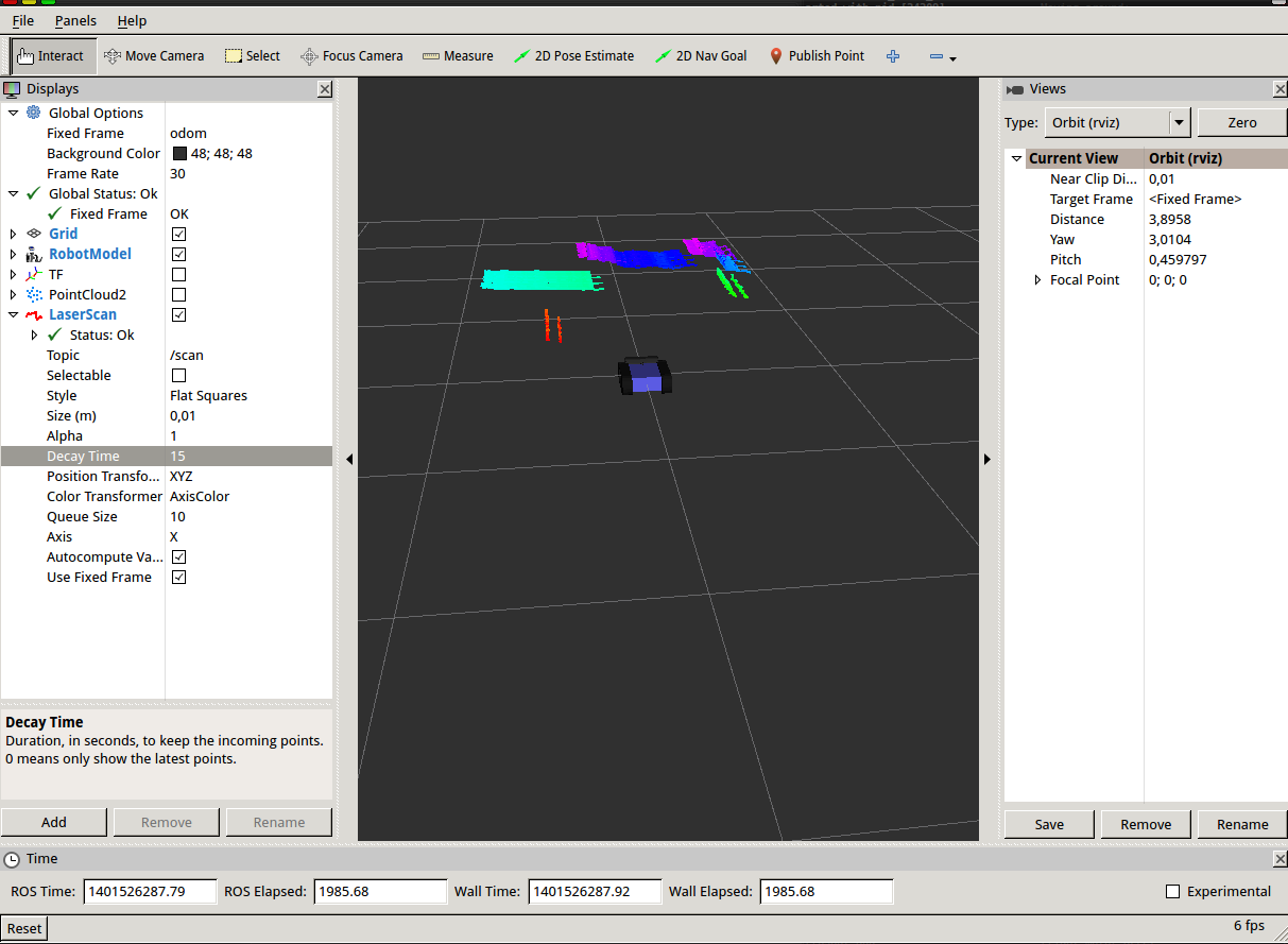
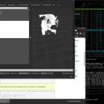
- driving further adding a decaytime of 10

-
- and activated point cloud
-
- the laserscan shows data according to the camera position relative to the robots base link
I will explain the robots hardware setup in another post as soon as its possible to run it by keyboard teleop while publishing its accurate odometry. Odometry Messages aren’t simply ROS transformations like moving parts of the robot. Because the robot belongs to the physical world where for example friction exists and further wheel jamming could happen, all the calculated position data need to by verified. Qualified for this task is sensor data like Ultrasonic Sensor Ranges, motor potentiometer or stepper motor positions or Openni2 data provided by the [amazon &title=Xtion&text=Asus Xtion]. After publishing this Odometry messages to the /odom topic, the ros navigation packages can generate geometry/Twist messages to correct the position to mach the simulation again in case there has been some deviation.
More on this topic soon.


![Screenshot[amazon &title=CubieTruck&text=CubieTruck]](http://defendtheplanet.net/wp-content/uploads/2014/05/Screenshot[amazon &title=CubieTruck&text=CubieTruck]-e1400677470940.png)
