The Adafruit Motor Shield is a very well documented piece of electronics. Its capable of controlling 2 stepper motors or 4 dc motors with a additional possibility of moving 2 servo motors at once(!). So its perfect for small robot projects!
It has four phases of 1,4 Amps maximum current each with an even higher peak current – in case you cool it for instance by a fan it should even take more regular current like the chips datasheets promise. The voltage of the motors should be between 5 and 12 Volts (can be increased to 13 like most car batteries do have at least as long as I’ve connected it to mine for about 30 minutes).
The coolest thing about it is the I²C protocol (and the connected build in PWM-Chip) it speaks. Because of that its stackable with for instance other motor shields and can drive up to 96 Motors with a single i2c signal giver.
In most cases the signals come from the arduino family, more precisely the Duemilanove, Diecimila, Uno (all revisions), Leonardo and Mega/ADK R3 and higher. As you might recognized, there is no arduino micro in the list, but as it is just a smaller version of the Leonardo it should be possible to work too – right? The answer is: yes it does – at least if you solder right and find the connections that need to be made since the SDA and SCL Pins are digital 2 and 3 on the Micro and A4 and A5 on the shield. Adding 5V, 3V and ground is enough to get it running. (But keep an eye to short circuits and separate powering circuits for the micro)
The i²c protocol (I-squared-C) is supported by the [amazon &title=Raspberry Pi&text=Raspberry Pi] and the [amazon &title=CubieTruck&text=CubieTruck] which means hypothetical it should be possible to run the motor shield with that devices too, but I would not recommend to do so, as there is nearly no code library at the time of this post beeing written.
-
-
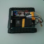
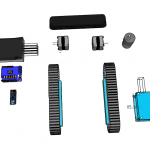
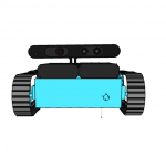
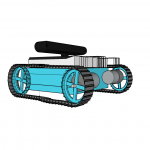
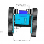
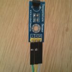
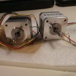
12V 350mAh per phase stepper motors
-
-
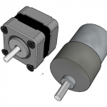
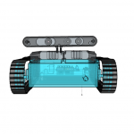
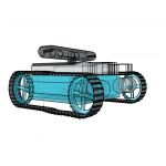
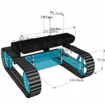
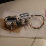
12V 350mAh per phase stepper motors
-
-
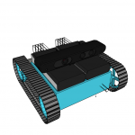
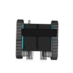
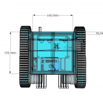
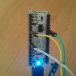
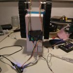
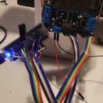
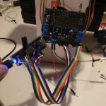
the arduino motor shield v2 attached to the Motors
-
-
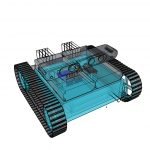
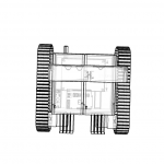
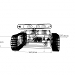
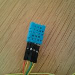
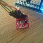
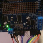
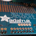
the motor shield close up
-
-
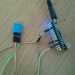
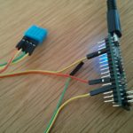
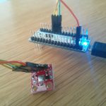
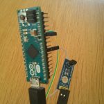
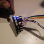
connections to the arduino Micro
-
-
connections to the arduino Micro
-
-
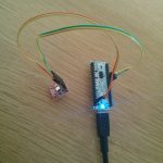
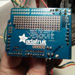
the Micro itself again
-
-
soldering isn’t something like driving the bike
-
-
you have to practise it a bit everytime 🙂
The motor shield comes with an arduino library where everything gets explained very well. Just one thing they forget to mention is the needed:
#define USE_USBCON
the motors
I’ve got to admit that the motors had been a bad joice so far – they are way to weak. I nearly drove me nuts to get them working, because I couldn’t believe how weak they are 🙂
So I’ve learned a lot about stepper motors datasheets and all of its very confusing unit handling the hard way. And I’ve done the mistake a lot of stepper motor newbies do: assuming the voltage needs to be the same as the batteries voltage. Avoid that thought in case you are building a robot currently 🙂